Quick demo of fully-modded Stern “Trident” pinball with new rules and sound

After getting my Trident operational, I installed the BSOS system and have been working on fine-tuning the custom code and sounds. Here’s a short demo of what the new Arduino-based controller does to a standard Bally 18/35/Stern early solid state game.

Resources (courtesy Dick Hamill):

The code is all available on GitHub. It’s broken down into a base library and then machine-specific implementations. Rewriting other games requires a moderate knowledge of C/C++.
https://github.com/BallySternOS

Here’s a suggested parts list. If you bought all these things, you could create 6 of these boards. If you don’t need that many boards, you might find cheaper ways to source smaller quantities. I haven’t done any work to figure out if this is the cheapest way to source any of this stuff.

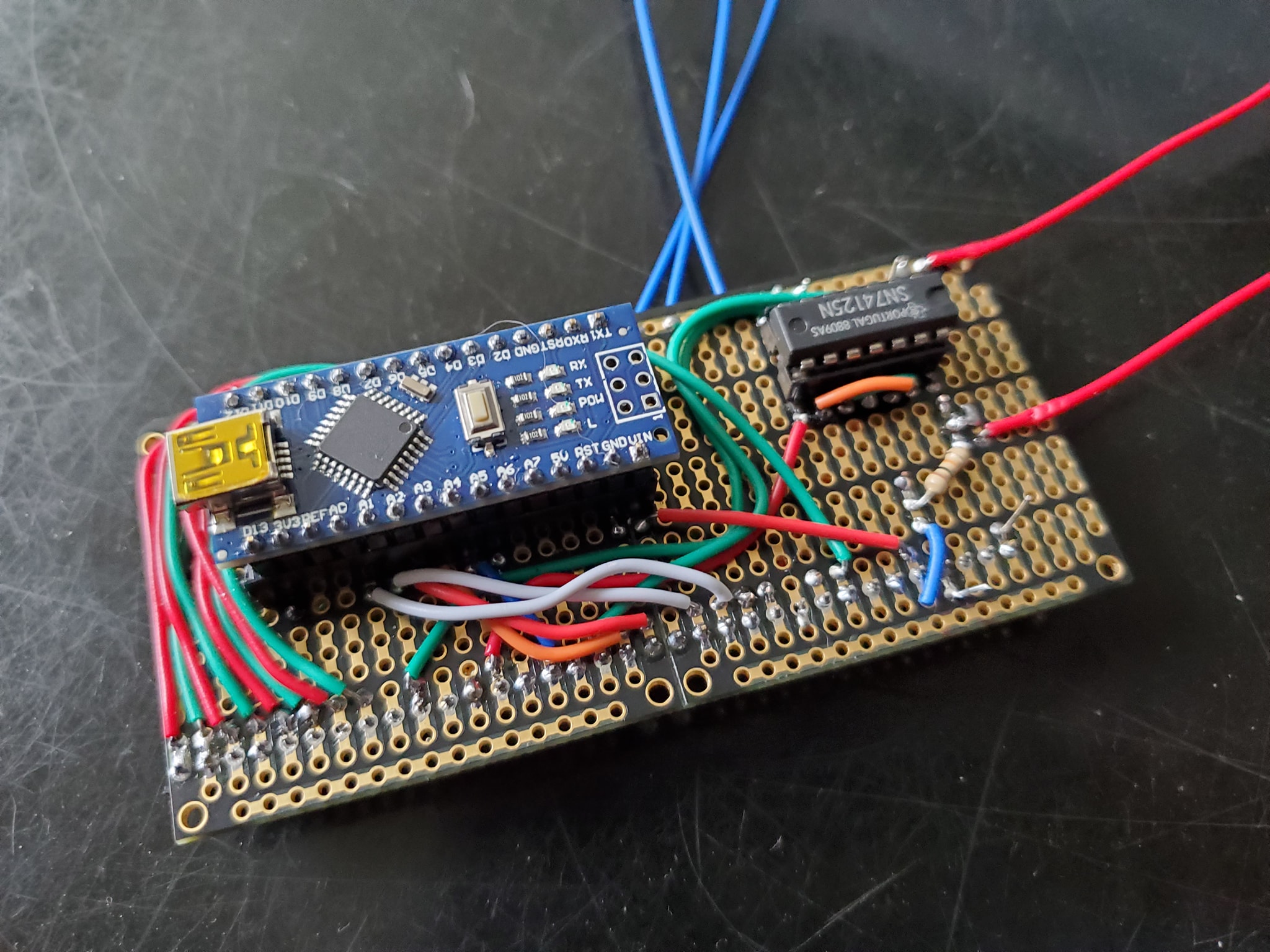
Cheap Arduino knockoff x6 ($20.99) – needs CH340 driver for programming / has to be ATmega328P
https://www.amazon.com/ATmega328P-Controller-Module-CH340G-Arduino/dp/B08NJNJCTX/

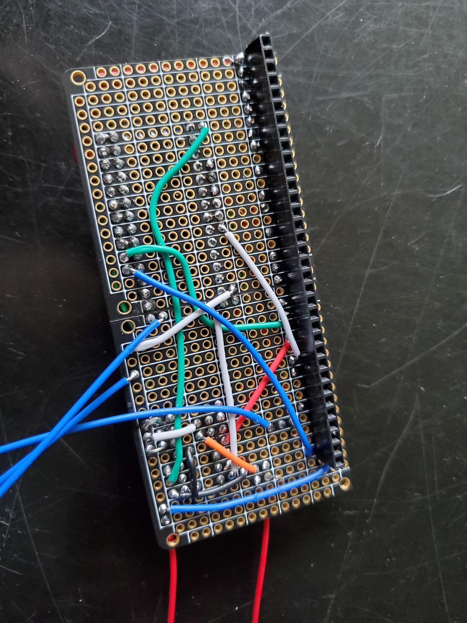
0.1″ 40-pin connector (40 pieces for $7.99)
https://www.amazon.com/Honbay-Single-Female-Connector-Arduino/dp/B06Y4S6G29/

32-pin Prototype PCB (2 pack for $9.99) – this won’t work for Alltek or MPU-200 because they have a 34-pin connector
https://www.amazon.com/Prototype-Snappable-Arduino-Electronics-Gold-Plated/dp/B081QYPHHP/

Wire ($7.99) – tons of wire
https://www.amazon.com/REXQualis-Breadboard-Assorted-Prototyping-Circuits/dp/B081H2JQRV/

74125 – ($1.95) https://www.jameco.com/z/74125-Major-Brands-IC-74125-Quad-Tri-State-Bus-Buffer_49373.html

Boot switch – x2 ($8.99) this switch will work for activating the Arduino board and toggling the speaker (see the writeup here to find out why: https://ballysternos.github.io/install.html)
https://www.amazon.com/gp/product/B07XMH174C/

OR

@RoyGBev has created a PCB and kit (doesn’t include the Arduino) here:
https://pinside.com/pinball/market/shops/1304-roygbev-pinball/04736-arduino-nano-adapter-for-classic-bally-stern

How to make a test bench rig for Bally-18/35 MPU boards using a PC power supply

I found this old video the other day and realized I didn’t have a post on my main site showcasing this video so I wanted to add it (also, this was before I learned the proper pronunciation of “Bally” LOL…. bah-lee).

Prototyping A Brand New Mata Hari Ruleset!

I’ve been working on a new project that I’m very excited about. There’s been a movement to create an inexpensive, non-destructive and simple way to mod early Bally/Stern solid state games and add more features. In this video, I demonstrate an early prototype of the system used to modify a Bally Mata Hari pinball machine to include new features such as a skill shot, modes and even a wizard mode.

Want to learn more about this project? Visit: https://github.com/BallySternOS

Repairing/Replacing a Stern/Bally Power Supply/Rectifier Board

As part of the ongoing restoration of a 1979 Stern “Trident” pinball machine, here’s a series of videos outlining how to replace the rectifier board on these games. This varies a bit between Stern and Bally due to wire color codes. References are here.

Source: PinWiki

Tracking down drop targets that won’t reset – Bally-35 “Mystic”

This is a game that’s been sitting in the back for awhile at my place that I keep meaning to get to, so I finally jumped back into to figure out what was wrong. It’s weird to go over notes you made 6+ months ago and try to pick back up where you left off — remind me not to do that.. LOL But the issue was relatively simple: The center bank of drop targets was not resetting.

In this series of videos, I go over, step-by-step the process of how to figure out what’s causing this problem, how to read schematics and manual diagrams, and the various points of failure, and once again, we are reminded of “Ockham’s Razor” which suggests the most obvious cause is the most likely… OR IS IT?

Interestingly enough, once I figured out where the problem was, rather than solve it the traditional way, I choose to do a “hack”… basically just to see if I could do it. The choice was, do you replace an entire 16-pin IC that’s only using one small part of it (involving adding a socket and a new chip that is pretty expensive and hard to find) or do you “hack” the damaged chip and piggyback a new component on top of it? Normally I don’t do these kinds of MacGuyver stuff on system boards, but it was a fun trick to try and it cost a few cents and about 10 minutes verses a lot more time than would have been used to replace a whole IC.

One reason why this hack job is particularly sloppy is because I had to work on the board in the game due to the previous owner having hard-soldered some wires to one of the connectors – that’ll be another future project to clean up all that mess, but for now, I needed to get this back working.

To understand what I did, here is a substitute circuit board showing the position of various individual 2N4401 transistors overlaid on the CA3081 IC package. Using this you can figure out where to insert a transistor manually on the IC pinouts if one of them fails: