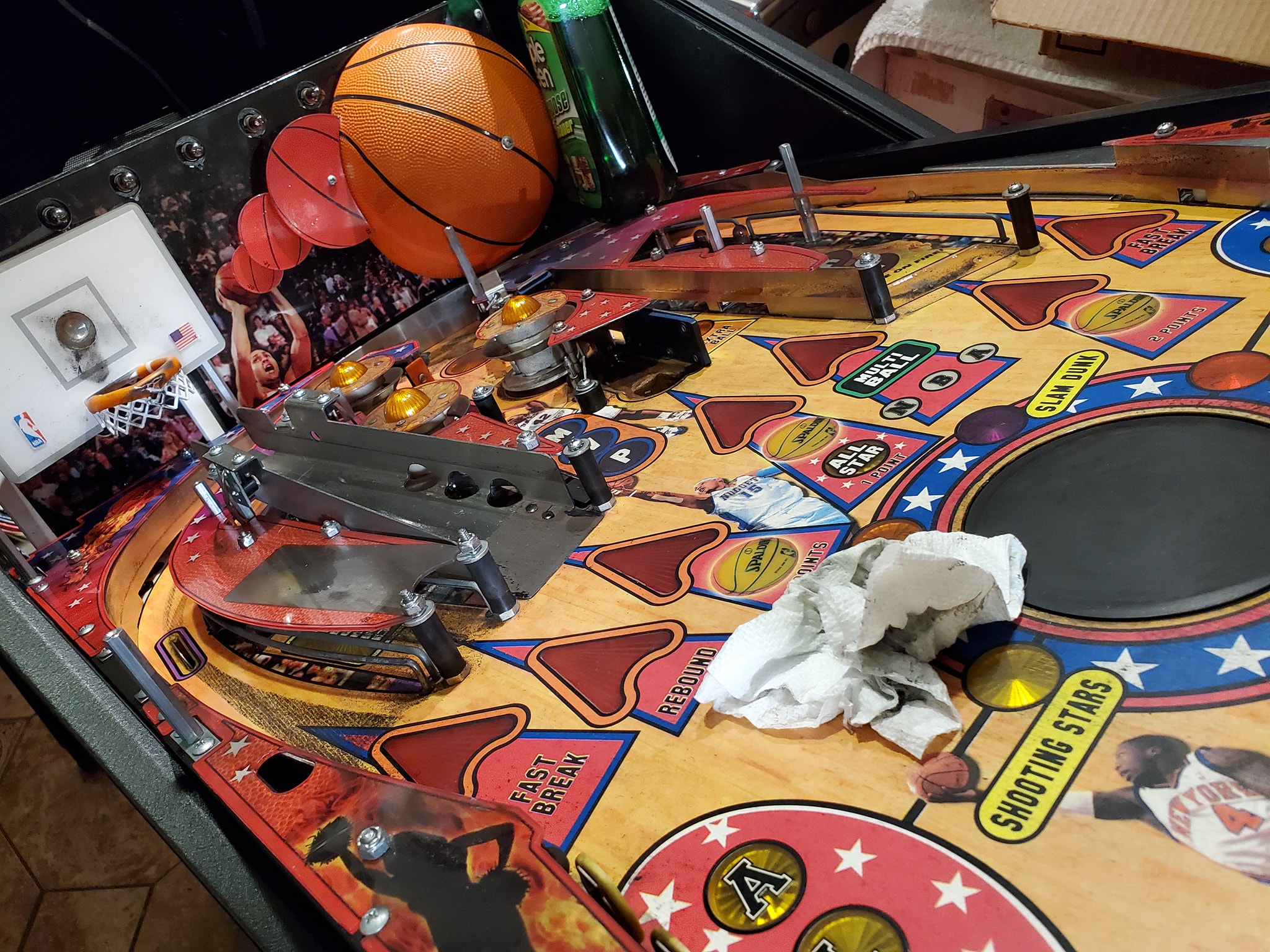
This is a very cool game that is surprisingly rare. A 2008 Stern “NBA”. Rumor has it the game had a very low production and was mainly made for the Chinese market.
I had a chance to get one of these games that had been stuffed in the back of an operators office for many years. It needed quite a bit of work. Here is the whole video series from first look, to the repairs, to the showcase of gameplay:
Now that I’ve got Haunted House running, it’s time to bulletproof the game – ideally you’d probably want to do the ground mods from the very beginning because in some cases, you might not be able to get the game working otherwise, but in this case, I managed to get the game to boot and appear to play well, so now we’re doing the required ground modifications to make the game more stable and reliable.
What’s actually involved in that?
It’s pretty simple. Gottlieb used single-sided edge connectors (unlike Trifucon which has contacts on multiple sides) for most of their connections. Over time, these connectors tended to fail, either by the contact surface becoming oxidized, or the blades becoming fatigued and not making good contact. Since ground is so important, without a solid contact, the game can behave in a variety of different and unpredictable ways, from random reboots, to intermittent issues with everything from lights to sound to coil firing. The general rule with Gottlieb games is if you’re having a weird problem that isn’t consistently repeatable, there’s a good chance it’s related to the powertrain. The most obvious culprit in the power chain is going to be the ground/return lines.
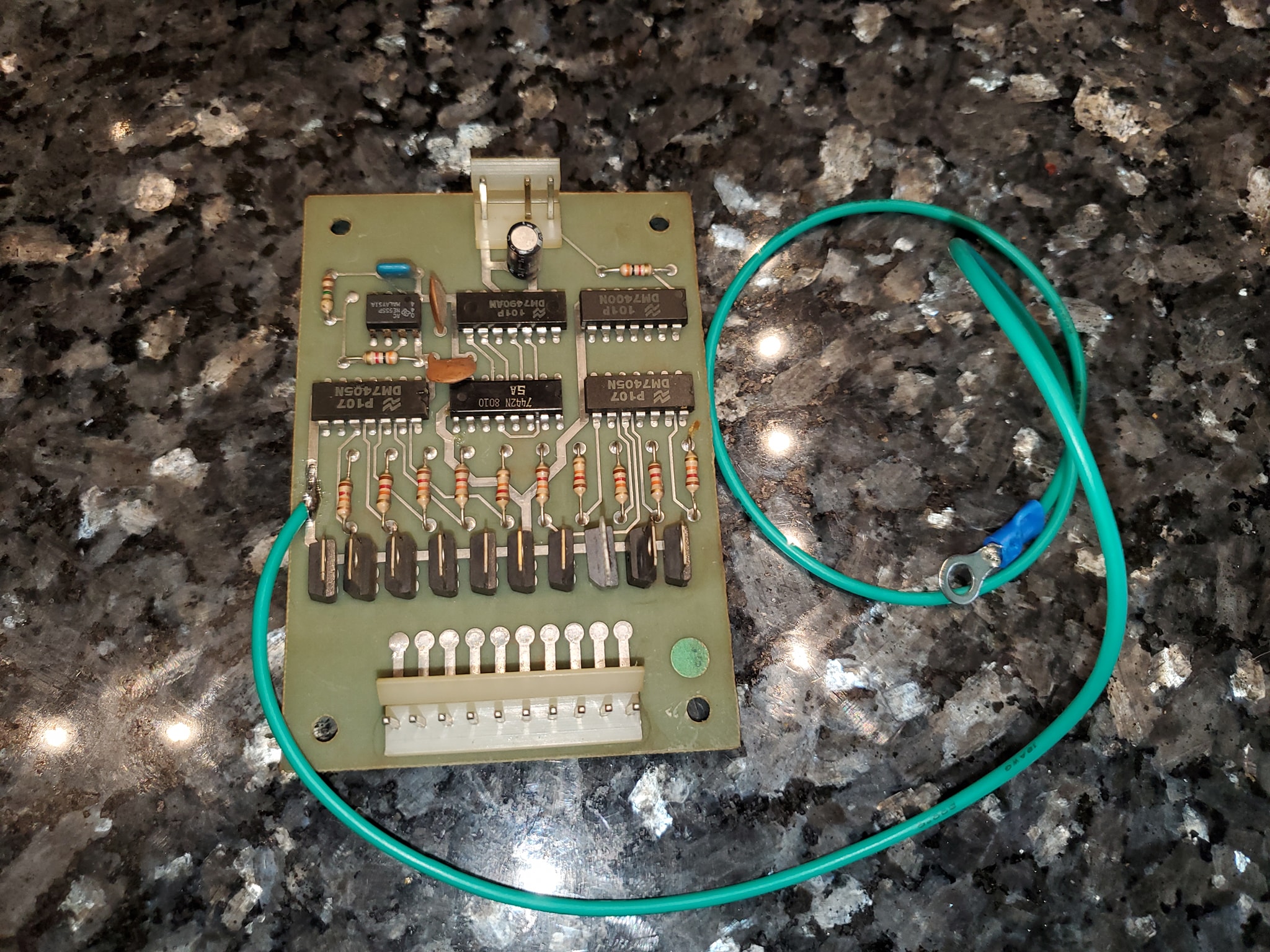
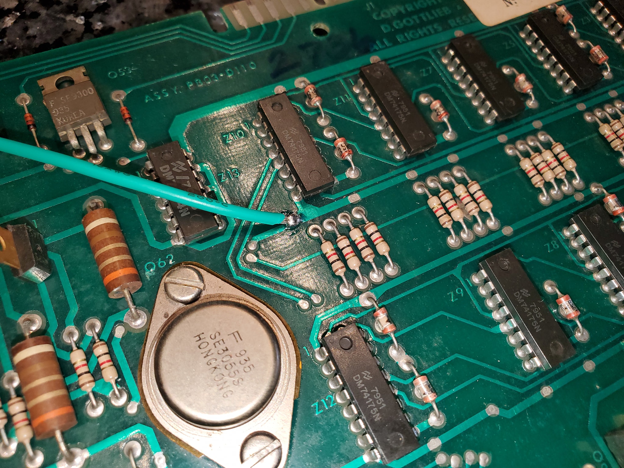
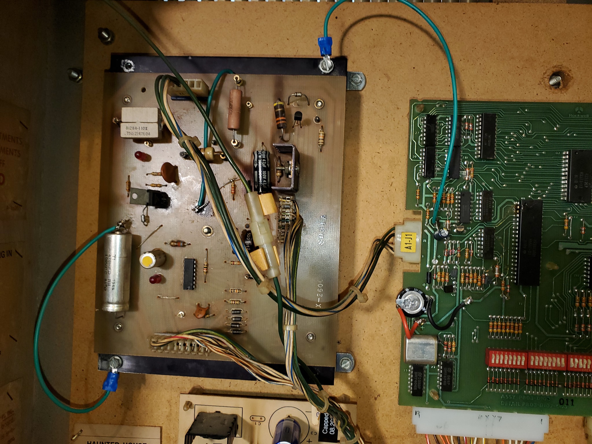
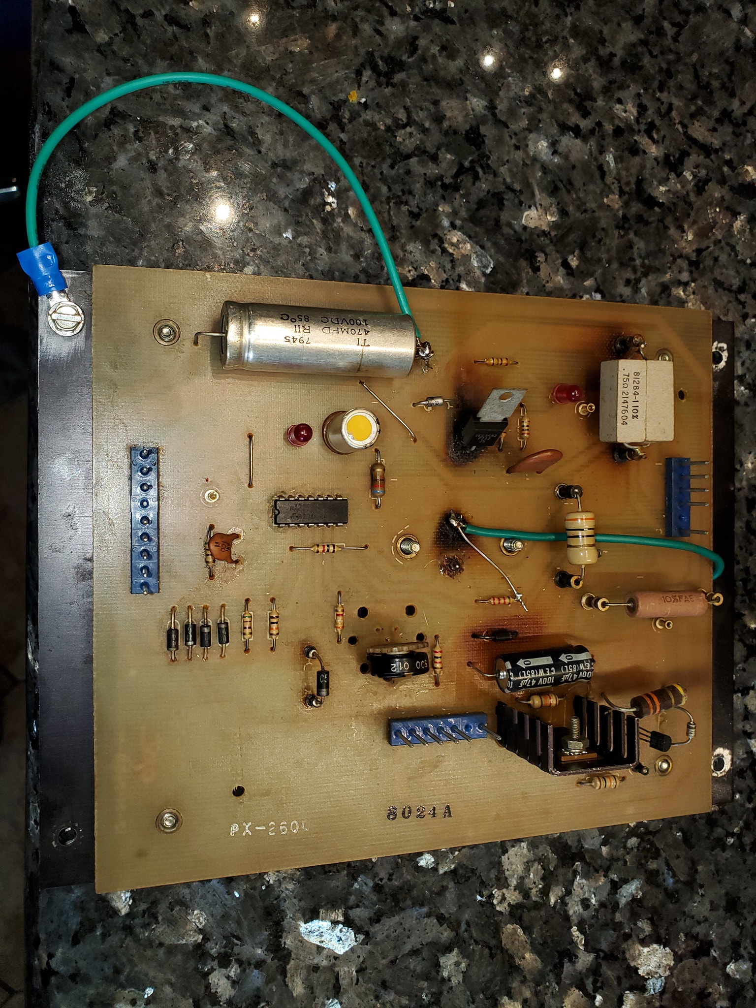
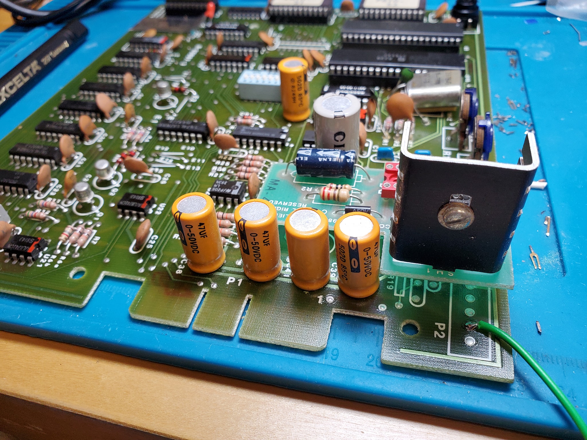
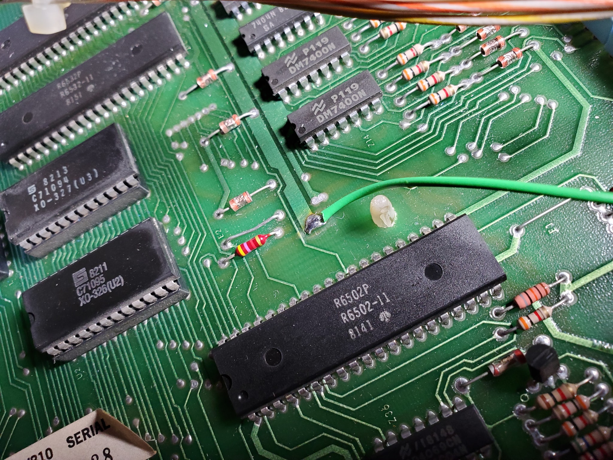
In-a-nutshell, the ground mods involve running an extra ground wire to tie all the different board’s ground lines to a common ground, and tie the head and the cabinet ground lines together — the only exception is you keep the 45v solenoid ground line separate (this is to ensure that if there’s a coil short, it doesn’t send high voltage to the rest of the game’s more sensitive components). Each board has a different recommended spot where you should tap into the ground, often it’s near one leg of a capacitor (which should also be changed if they’re original). Use 18 gauge wire (preferably green colored) and tap into each board with one end in the designated spot, then crimp a spade terminal on the other end and tie all the boards to a single ground plane (usually the metal bracket that mounts the power supply in the upper left corner — be sure to sand the paint off the area so you can make contact (alternatively you can also solder directly to the bracket.
Once you have all the boards tied to a single plane, you want to tie that to the head and the cabinet, by running wires from the power supply bracket to the metal frame in the head, and then one down into the cabinet to the transformer board, where you’ll find a ground backplane you solder to (on System 80B games, you’ll also want to take all the ground wires that terminate on the transformer board and tie them together, preferably eliminating the molex connectors they used which cause problems).
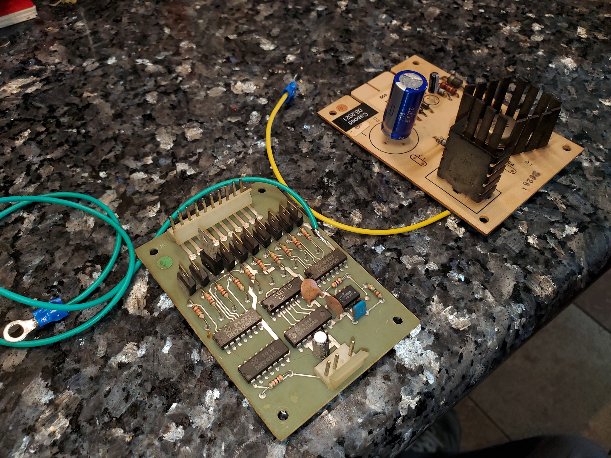
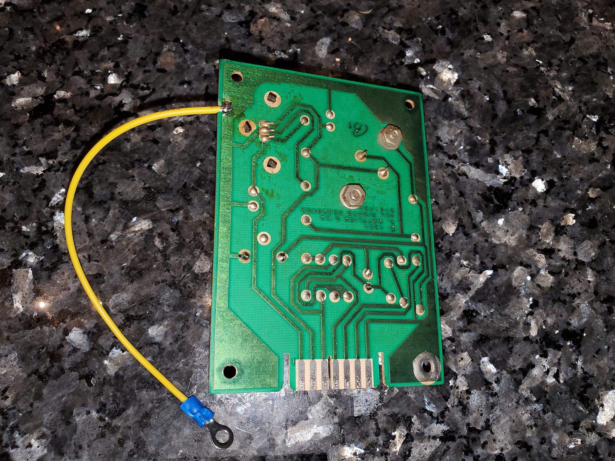
Click at the top of each image below for larger versions:
All the boards with mods – note the mpu board ground mod is to the top part of the capacitor on the left middleGround mods to the aux light board and sound card power supplyunderside of the sound board power supply showing ground tapaux light board ground tapNote the light green wire – this is the new ground line from the power supply bracket in the headground tap location on the driver boarddriver board ground tap completedlocation shown where protective coating is sanded off to solder ground tap on driver boardtap from MPU to main ground plane / power supply boardRecommended Gottlieb System 80 ground modifications – power supply boardSound and Speech board ground mod tapAlternate ground mod location for sys80 CPU board
This is part of the ongoing series of restoring a 1982 Gottlieb “Haunted House” pinball. From crazy wiring problems to system upgrades, I’m taking you along with me on this scary ride.
In this next series, I tackle one of the most intimidating problems: a huge mess of hacked wiring. Can we untangle this mess? Will the game actually work? Let’s find out!
This is a series of three videos covering before, during and after, demonstrating problems with Gottlieb System 80 pop bumper driver boards. There are some basic things you want to do to make them work better and more reliably.
Summary of Pop bumper board mods:
First, check to see if you have older, or revised boards and convert older versions to the new revised version
Replace 47uf cap with 100-200uf cap
Add a 4.7uf 10v cap on underside to help with “phantom pops”
Re-flow pin headers and make sure to remove any oxidation from the pins
Test the driver and replace with a Tip102 if needed
To reduce “ghost pops” you can add a 47uf (10v-16v) cap between the pins displayed below:
Anybody messing with pinball machines will undoubtedly encounter problems with flippers. Often they seem to get “stuck”, will stay up and not go back down or behave weird. We often instantly go to the flipper mechanism to look for a problem, but sometimes it’s not there.
Here is an update to my progress completely re-coding a 1979 Bally Paragon pinball machine, with an Arduino Nano, with all new rules and operating system. This game will be an enhanced version of the original with extra features and deeper modes, and 14-channel polyphonic CD-quality sound.
This is an introduction to an up-and-coming technology that a small group of pinball and electronics enthusiasts are developing. A custom microcontroller that interfaces with Bally-35 MPUs and allows you to write customized rulesets, even completely re-theming games. This is the first part of a journey that I hope to take everybody on.
NOTE: This is a video I recorded several months ago that I forgot to make public, so I’m much further along.. But thought it might be interesting to show this early look at the development of this technology. Now there are etched boards that can be acquired.