Recommended Gottlieb System 80 Ground Mods (Haunted House – Part 9)

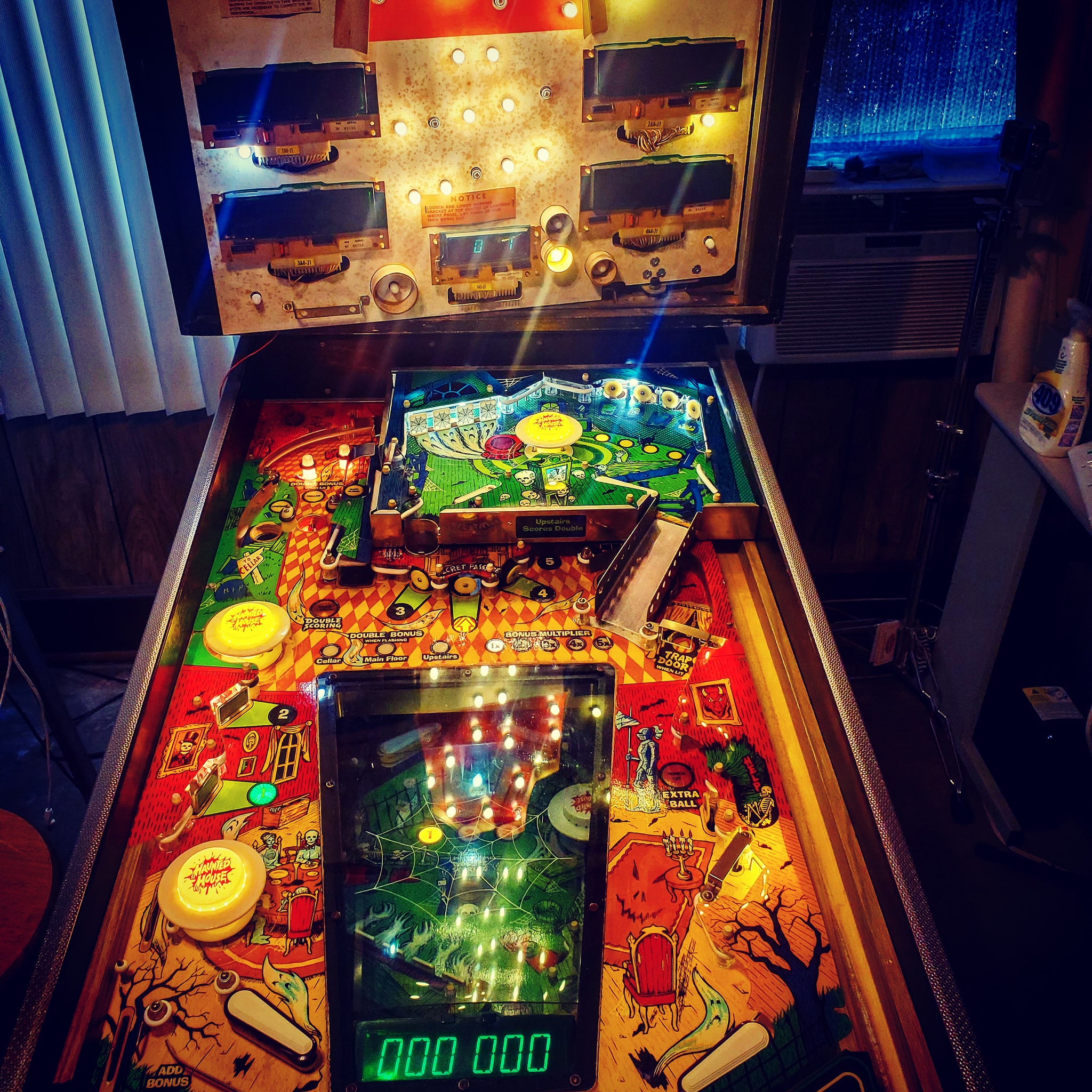
Now that I’ve got Haunted House running, it’s time to bulletproof the game – ideally you’d probably want to do the ground mods from the very beginning because in some cases, you might not be able to get the game working otherwise, but in this case, I managed to get the game to boot and appear to play well, so now we’re doing the required ground modifications to make the game more stable and reliable.

What’s actually involved in that?

It’s pretty simple. Gottlieb used single-sided edge connectors (unlike Trifucon which has contacts on multiple sides) for most of their connections. Over time, these connectors tended to fail, either by the contact surface becoming oxidized, or the blades becoming fatigued and not making good contact. Since ground is so important, without a solid contact, the game can behave in a variety of different and unpredictable ways, from random reboots, to intermittent issues with everything from lights to sound to coil firing. The general rule with Gottlieb games is if you’re having a weird problem that isn’t consistently repeatable, there’s a good chance it’s related to the powertrain. The most obvious culprit in the power chain is going to be the ground/return lines.

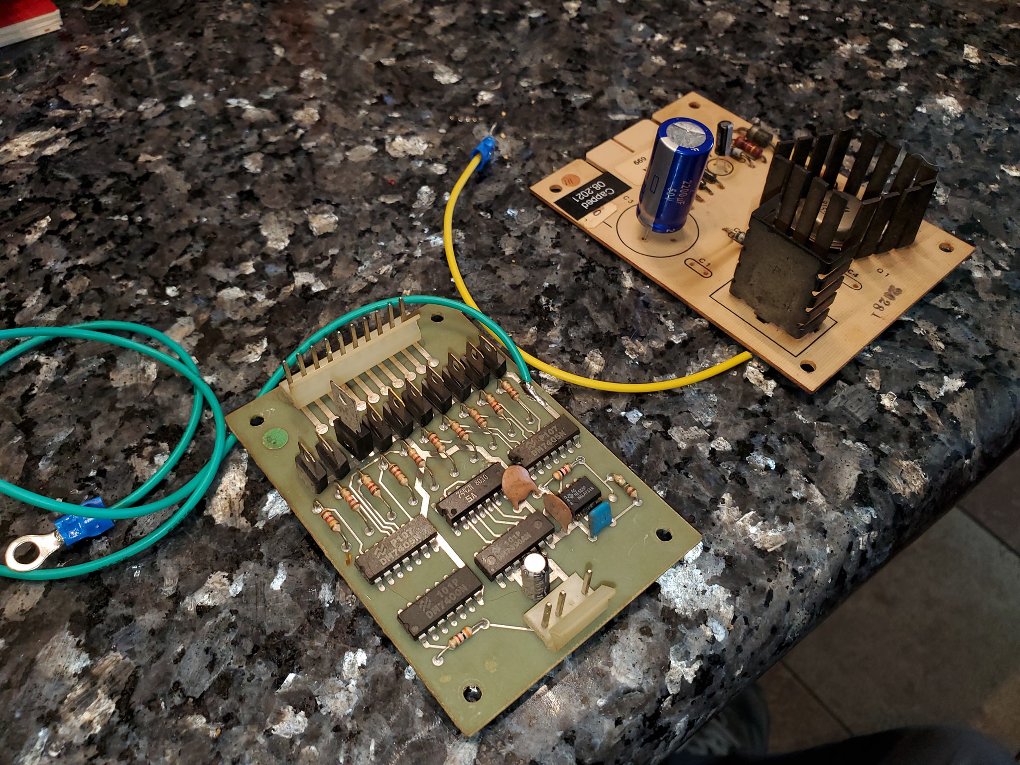
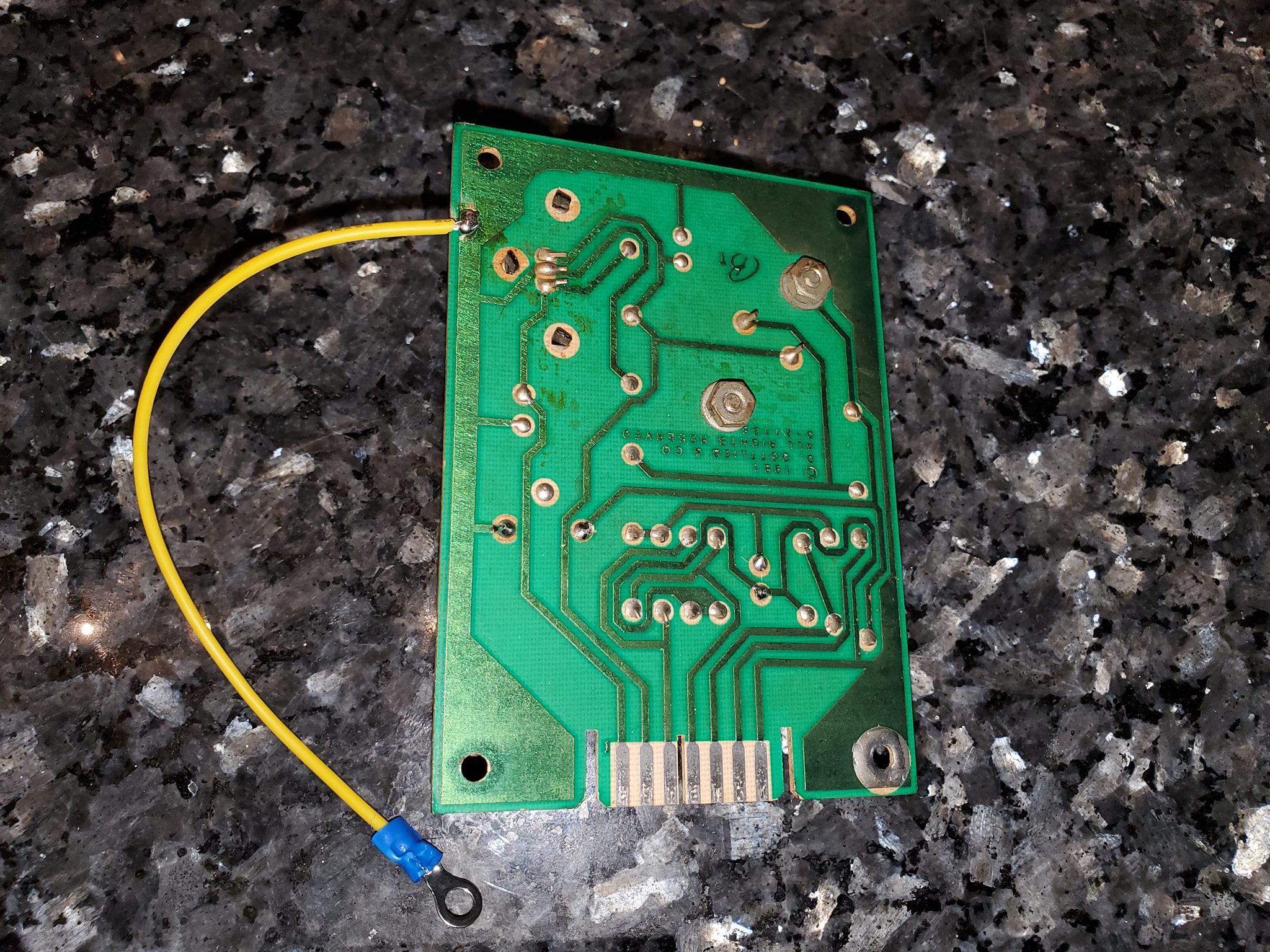
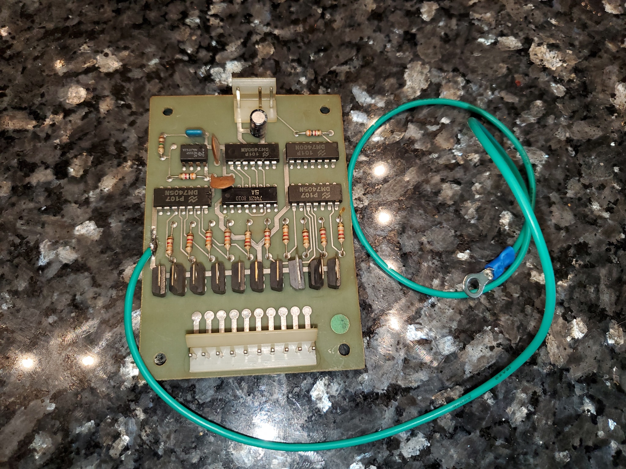
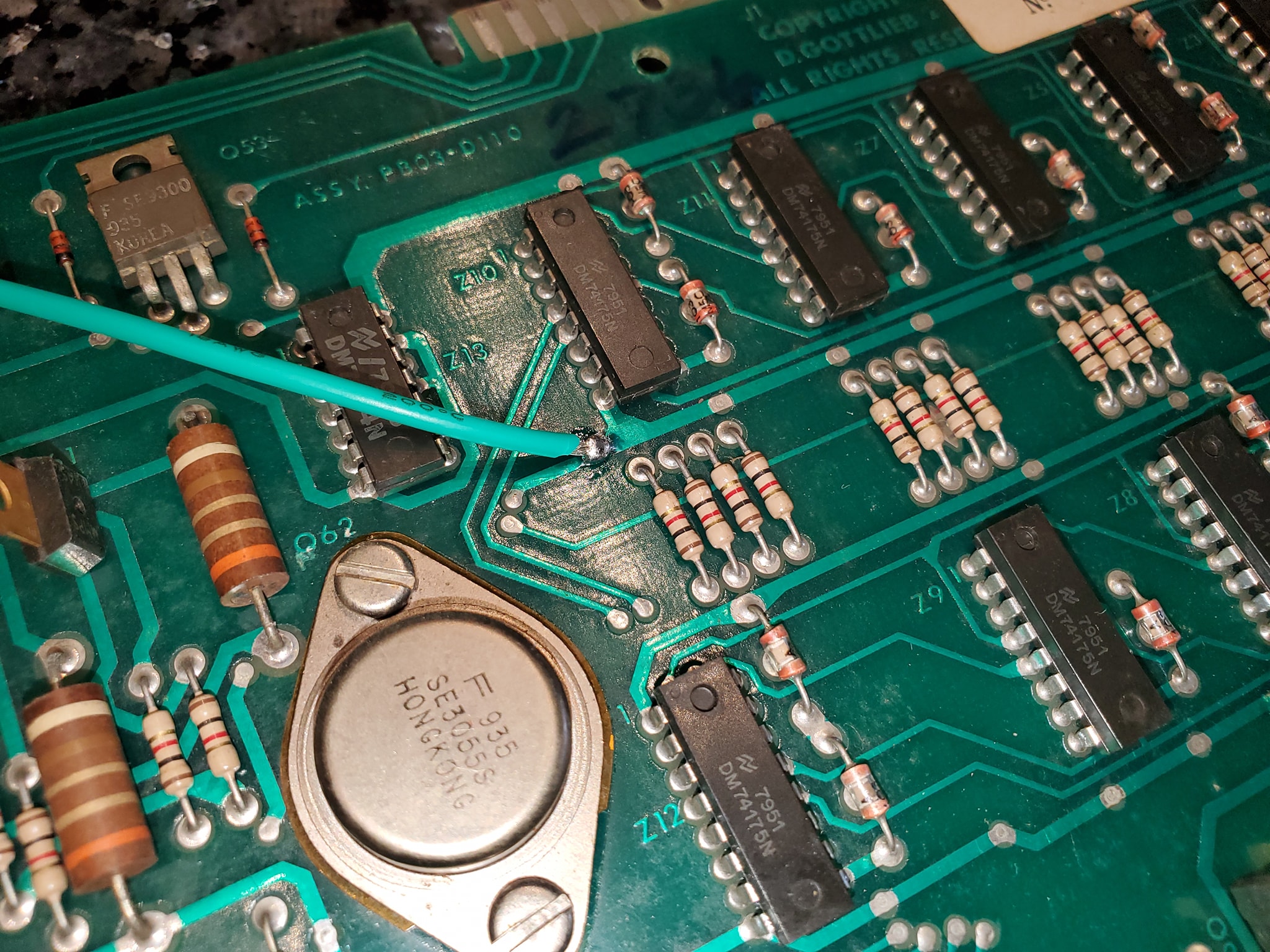
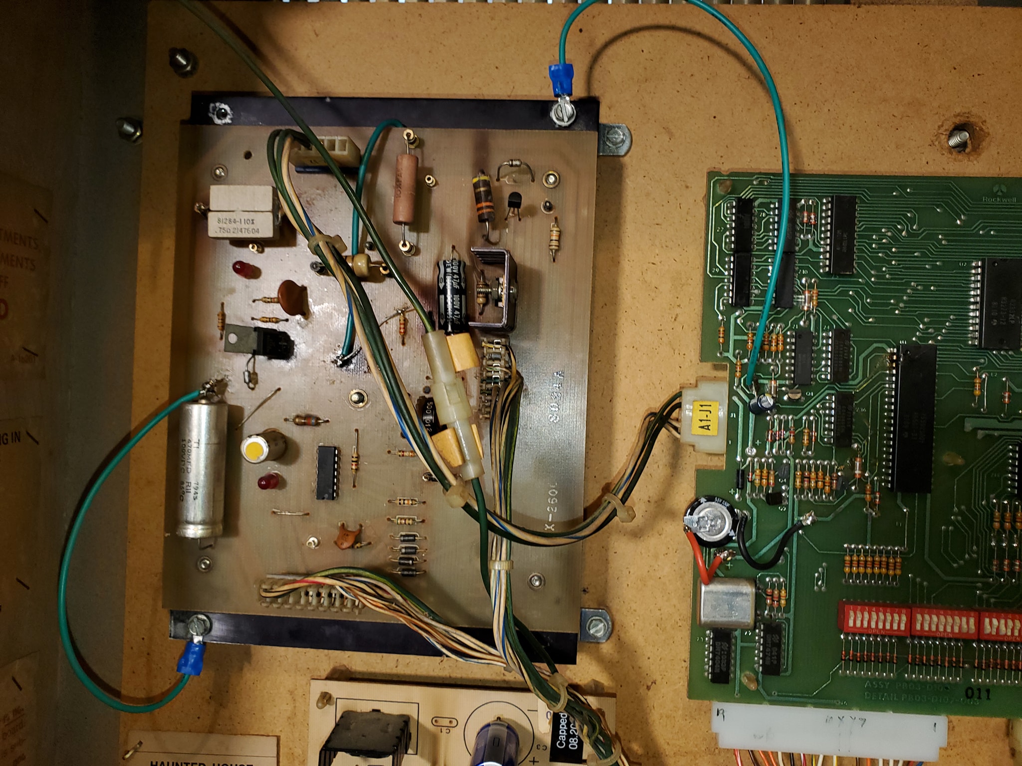
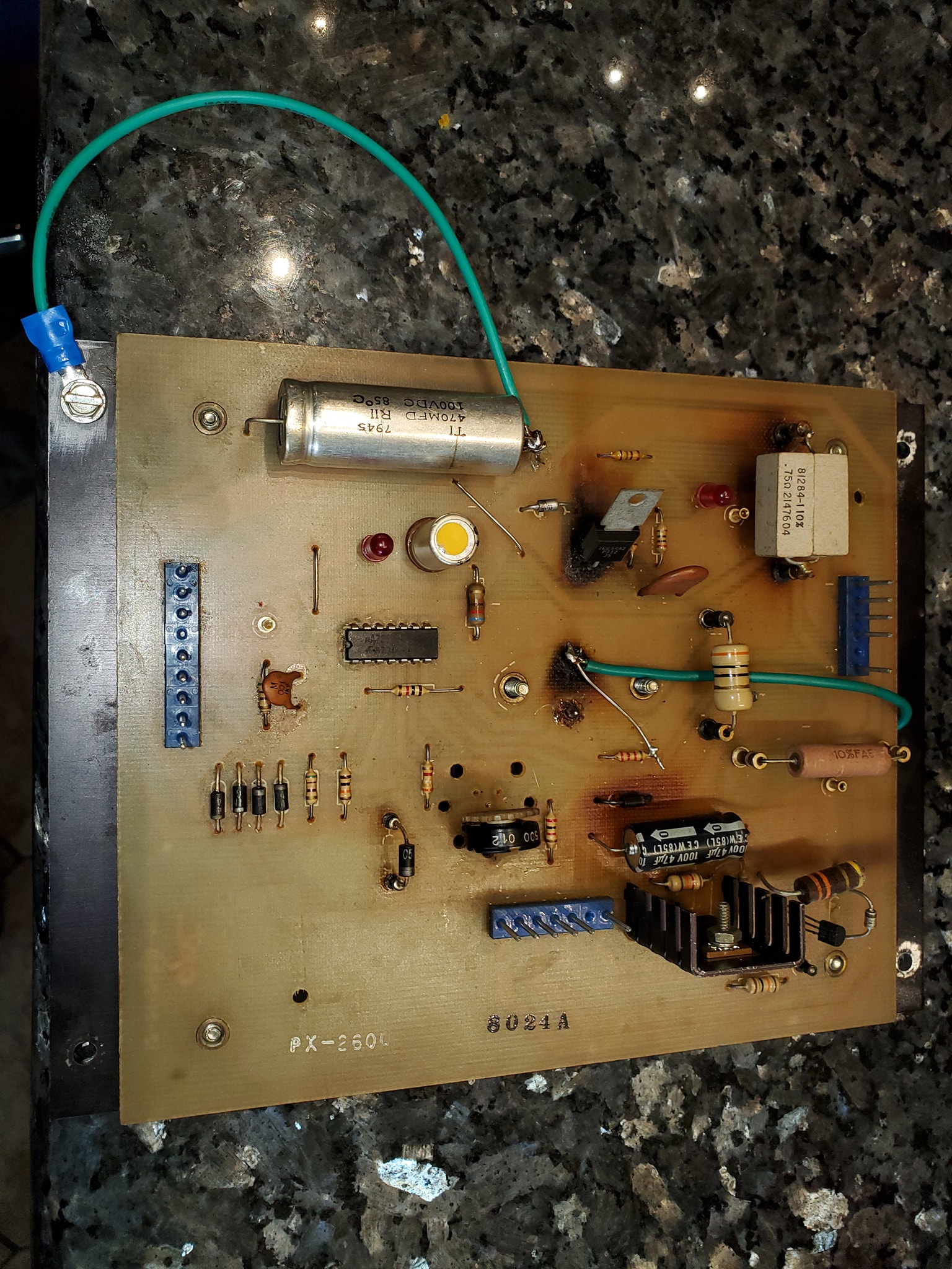
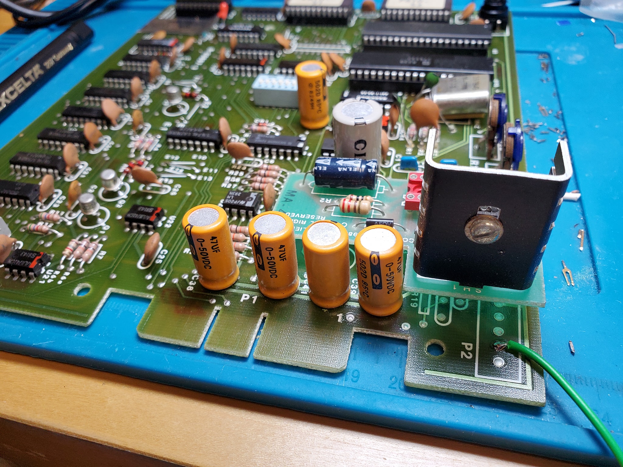
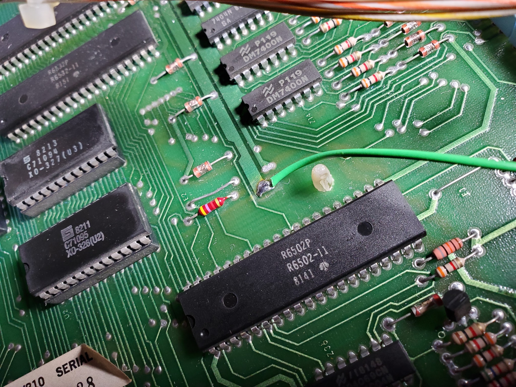
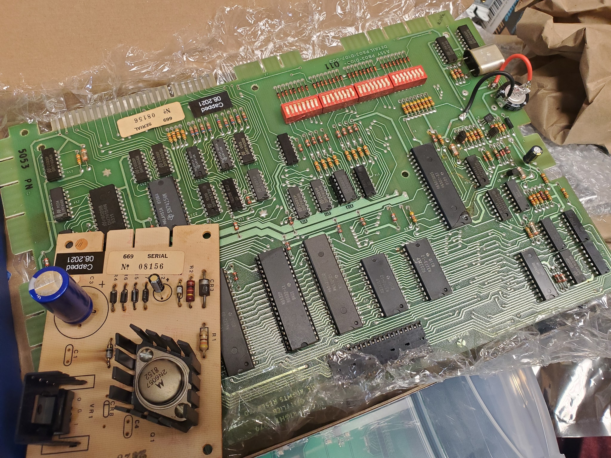
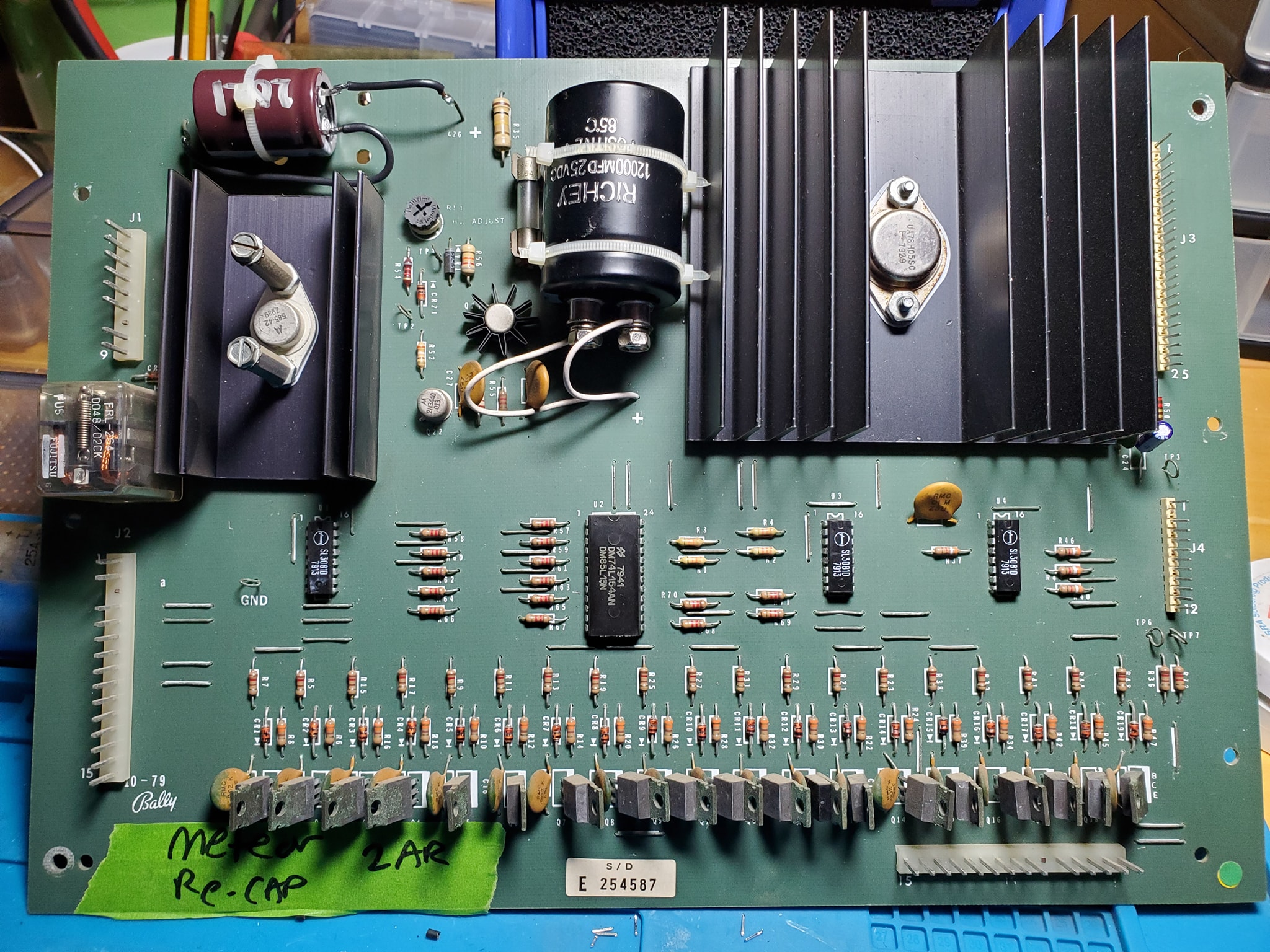
In-a-nutshell, the ground mods involve running an extra ground wire to tie all the different board’s ground lines to a common ground, and tie the head and the cabinet ground lines together — the only exception is you keep the 45v solenoid ground line separate (this is to ensure that if there’s a coil short, it doesn’t send high voltage to the rest of the game’s more sensitive components). Each board has a different recommended spot where you should tap into the ground, often it’s near one leg of a capacitor (which should also be changed if they’re original). Use 18 gauge wire (preferably green colored) and tap into each board with one end in the designated spot, then crimp a spade terminal on the other end and tie all the boards to a single ground plane (usually the metal bracket that mounts the power supply in the upper left corner — be sure to sand the paint off the area so you can make contact (alternatively you can also solder directly to the bracket.

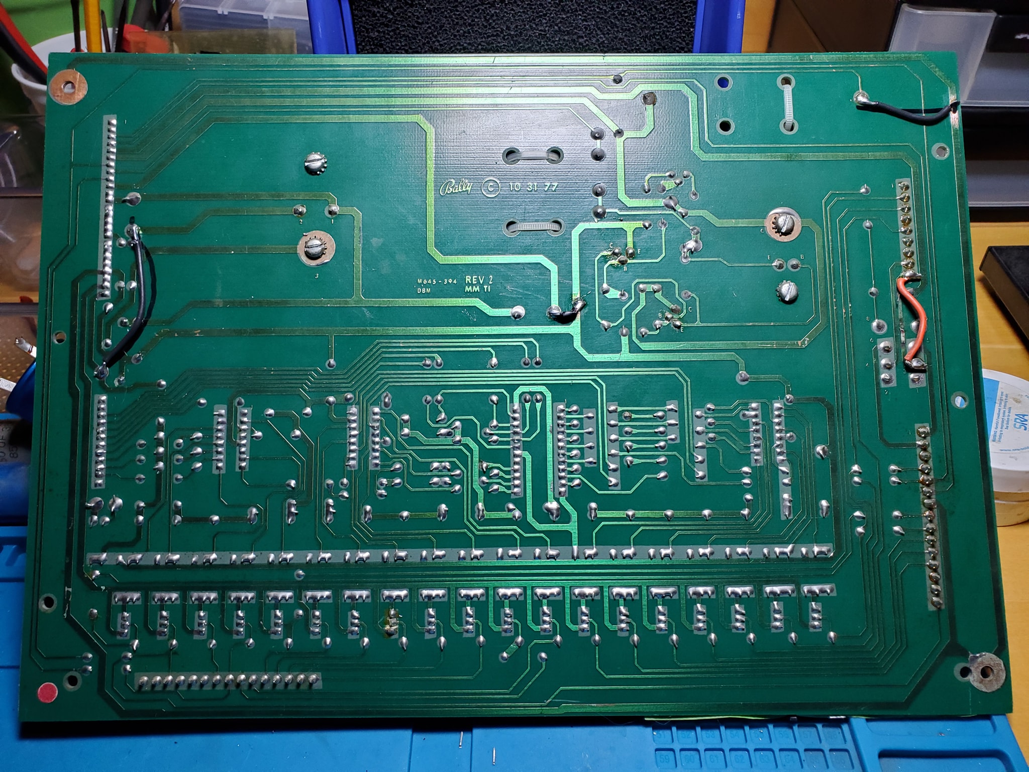
Once you have all the boards tied to a single plane, you want to tie that to the head and the cabinet, by running wires from the power supply bracket to the metal frame in the head, and then one down into the cabinet to the transformer board, where you’ll find a ground backplane you solder to (on System 80B games, you’ll also want to take all the ground wires that terminate on the transformer board and tie them together, preferably eliminating the molex connectors they used which cause problems).

Click at the top of each image below for larger versions:

Sound and Speech board ground mod tap
Alternate ground mod location for sys80 CPU board

Haunted House Pinball (Part 8) – Review of System 80 Boards and Demo of Play

As work continues on the restoration of a 1982 Gottlieb Haunted House pinball, I’m finally seeing progress and have the game working. So in this video, I go over each of the boards in the backbox, what their function is, and what work I’ve done thus far. Then I demo the operation of the game, sound and gameplay.

In the next video, I will cover the ground mods to “bulletproof” the game.

Building a custom micro-controller for early Bally/Stern solid state pinball machines

This is an introduction to an up-and-coming technology that a small group of pinball and electronics enthusiasts are developing. A custom microcontroller that interfaces with Bally-35 MPUs and allows you to write customized rulesets, even completely re-theming games. This is the first part of a journey that I hope to take everybody on.

NOTE: This is a video I recorded several months ago that I forgot to make public, so I’m much further along.. But thought it might be interesting to show this early look at the development of this technology. Now there are etched boards that can be acquired.

Recommended mods to Bally-18/35 and Stern solenoid driver boards

In today’s episode, I go over some standard, recommended modifications to the Bally-35 series solenoid driver board. There are over 60 popular pinball games that use this hardware setup and these quick modifications will help make the game run better and more-reliably. They involve adding three jumpers to the board. Whenever I have a chance to work on one of these boards, I do these mods.

Here are some front and back pictures of both Bally and Stern Solenoid driver boards. The black wires are the mods. The other colored wires are done by operators having to do with the coil lockout relay.

Bally Solenoid Driver board
Stern Solenoid Driver Board

Work continues on the Bally Mr. & Mrs Pac Man Pinball Game

In the continued saga of bringing this 1980s game back to life, I begin to go over the electronics and figure out why the game wouldn’t boot up.  Normally you fire up these Bally machines and count the number of times the LED on the MPU board blinks, but in this case, the game didn’t even get far enough to begin to start up the MPU.  Fuse F3 kept blowing and the game wouldn’t power up at all…

An examination of the schematics showed an area on the power rectifier board where it was likely some components were damaged and needed to be replace.  Luckily, these were not very obscure items so I could pick them up easily.

Stay tuned for the next installment where I go into addressing an issue with a broken plastic rail guide that probably can’t easily be replaced, so I have to fabricate my own!


Fixing a dead dot matrix display board

The other day the DMD just went “poof” on one of my machines.  After doing a little research, and checking connections and things, I realized the DMD board died.  In this installment, I walk through the process of rebuilding the power supply-portion of a Bally/Williams WPC DMD board.  In part 1 I describe what I’m doing and introduce you to the tools I’m using.


Next up, let’s talk about using a meter to check circuit board traces as we go along..

Desoldering and replacing components.

Now the moment of truth!  One thing I want to add is pay very close attention to each item you are replacing on these boards.  Two diodes, capacitors or transistors may look alike, but have slightly different values or part #s.  The three power transistors and the diodes are not all the same.  You may have to bust out a magnifying glass to note the different in the markings on each part.  This should also be cross-referenced with the schematics and/or parts list from the game manual.