In this video I dive into diagnosing an error condition with a 48v node board for Stern’s Spike 2 pinball system. In this case, I have a Jaws Pro where most of the switches went out and a lot of coils stopped working. The machine says “Node 9 not found” so we’re going to take a look at what the problem is.
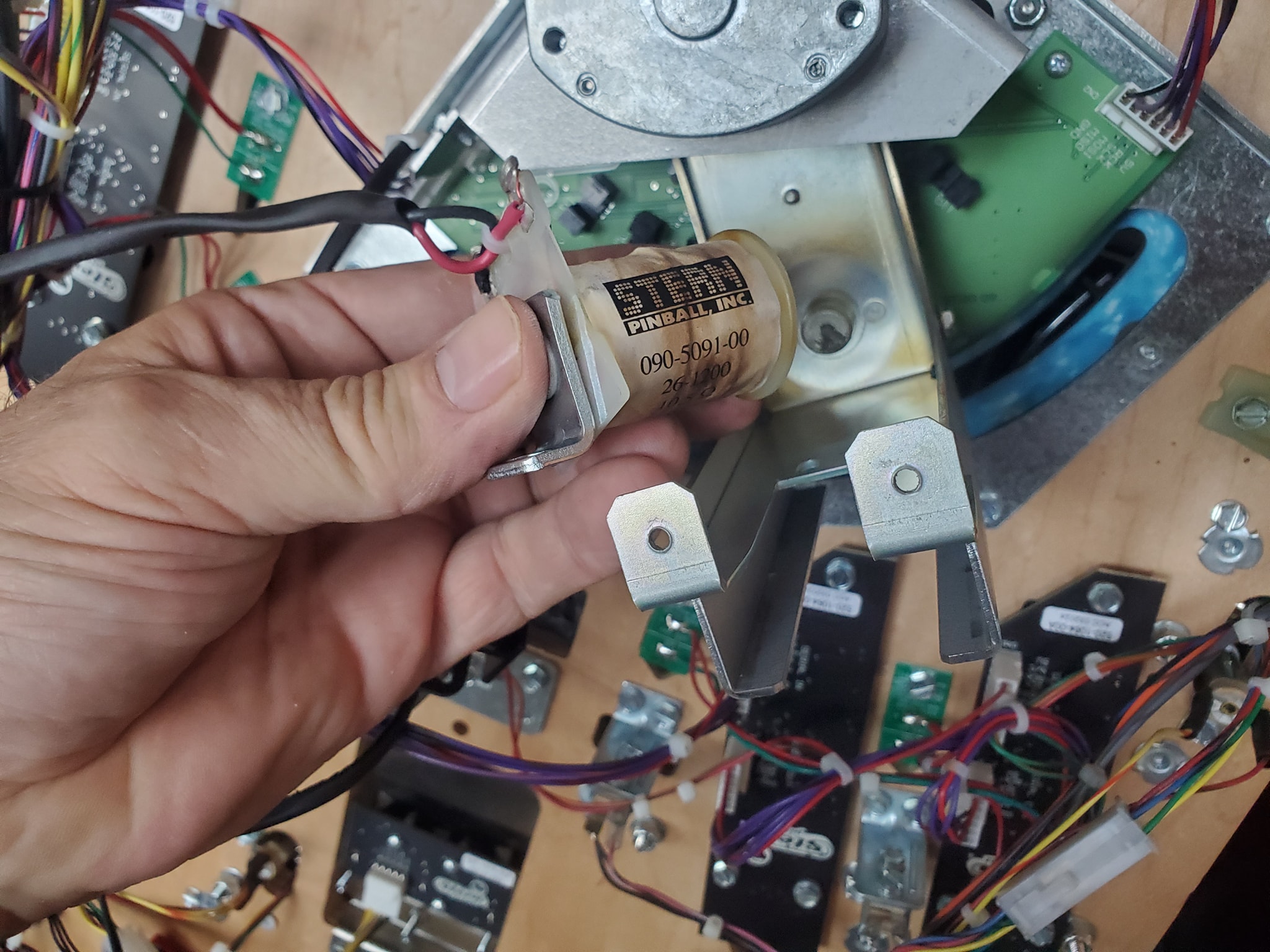
The fin up kicker coil was fried and shorted.
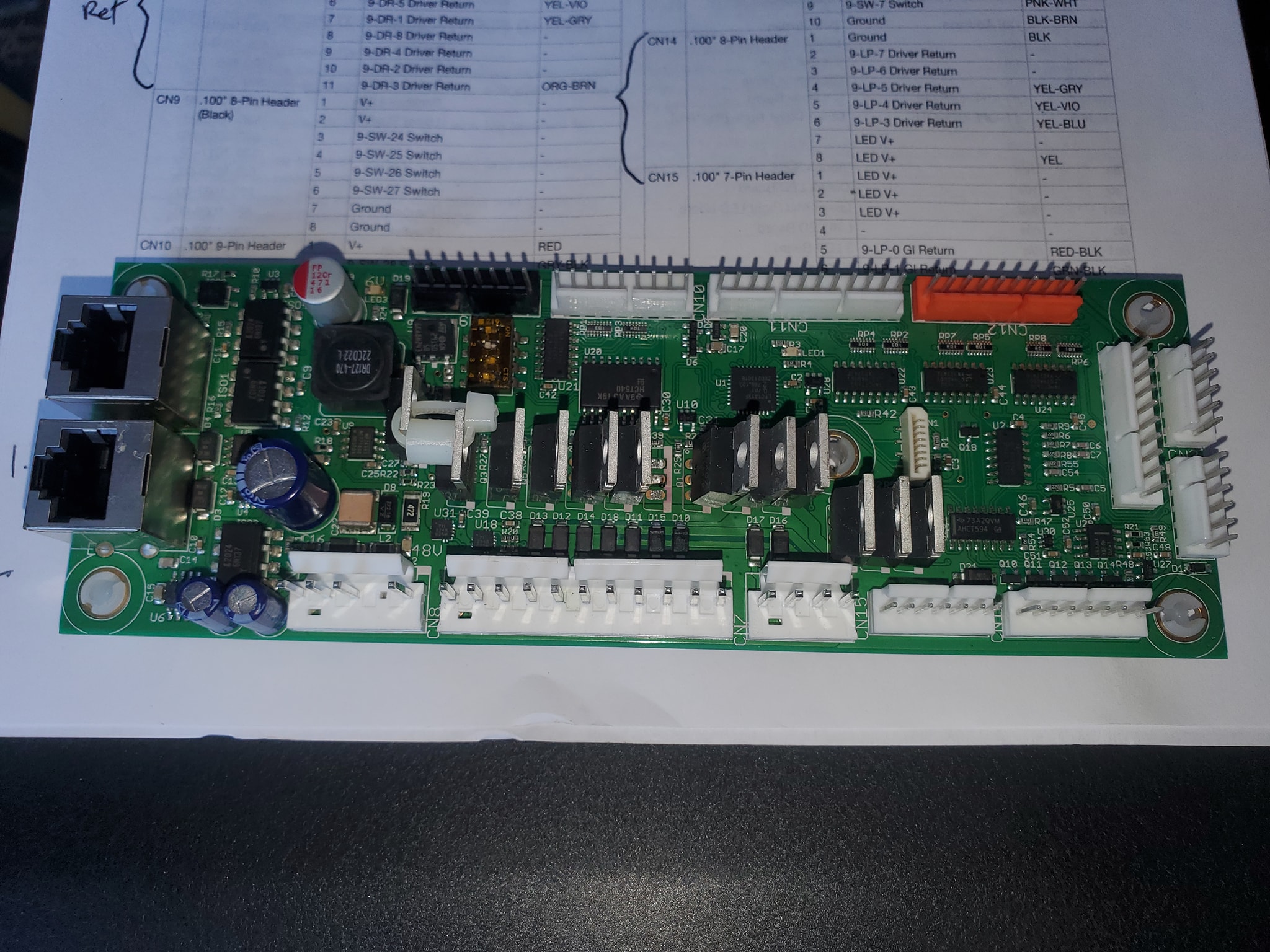
Here is the damaged Node board 9 – there’s a driver transistor that exploded and isn’t there in the middle
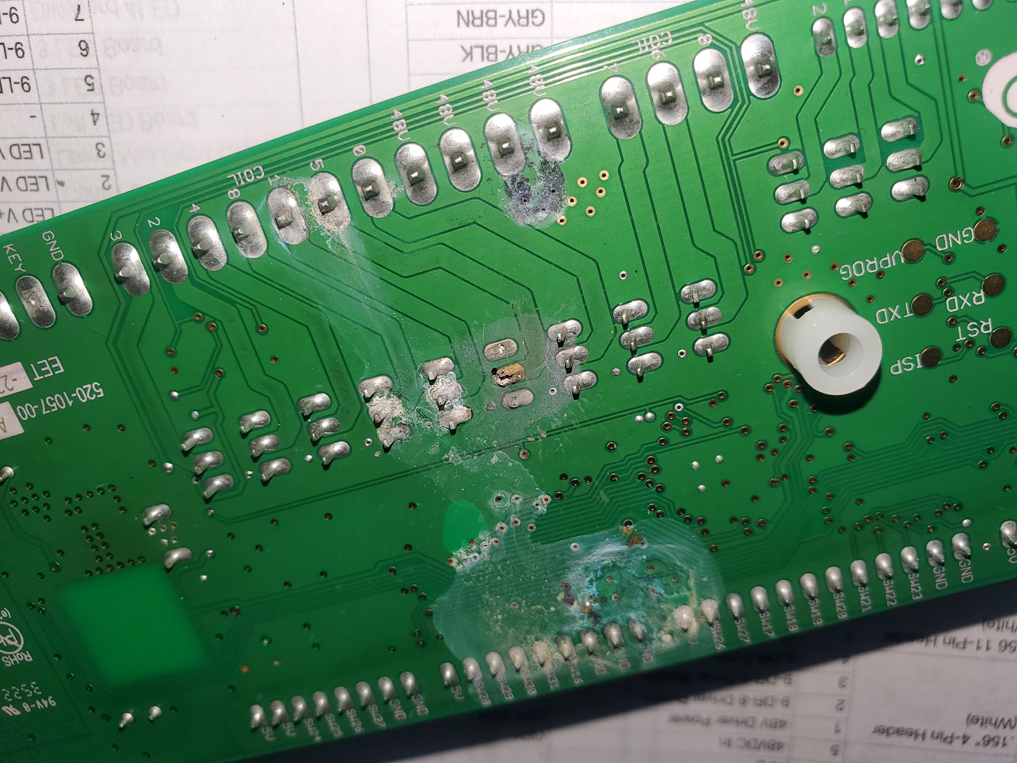
On the underside of the node board, there was a bunch of corrosion. The problem is, there’s no indication of where this came from? It’s at the top of the playfield underneath the playfield, not near any area where any cleaning solvents could lead, and I didn’t use any cleaning solvents on the playfield. It must have come this way from the factory.
I’ve encountered an odd problem with this Stern Walking Dead pinball game. The sound completely went out. But there is not a dedicated sound board. So what do you do? It’s a lot scarier than one would think…. This is part one describing what’s going on and what I’m doing about it…
This is an ongoing series of videos showing my progress on rebuilding all the electrical components of a vintage Atari Star Wars arcade game. This includes rebuilding the power supply, the audio power board, the audio board, the MPU board, the display controller, the deflector board, the high power CRT board and other items.
NOTE: This is an ongoing series and more videos will be added to the playlist so be sure to subscribe and turn on notifications to receive updates of more progress.
Lately I’ve been doing some arcade repair work and here’s another project I’m messing with.
Today in the club I’ve got a beat up, original Ms Pac arcade game from a local bar. The owner of the bar wants it fixed and back online for people to play. So this is not a “restoration” as much as it’s a basic “repair”. I go over what the client wants and what we’re going to do. There are also a few surprises as you’ll see… in the next part, I end up retro-modding the game to make it even cooler.
One correction: on the Bitkit2, you do need to separately connect the power supply to the converter board. That converter board does not pull voltage from the Ms Pac harness to the Jamma side – it gets power from the molex .156″ connectors instead.
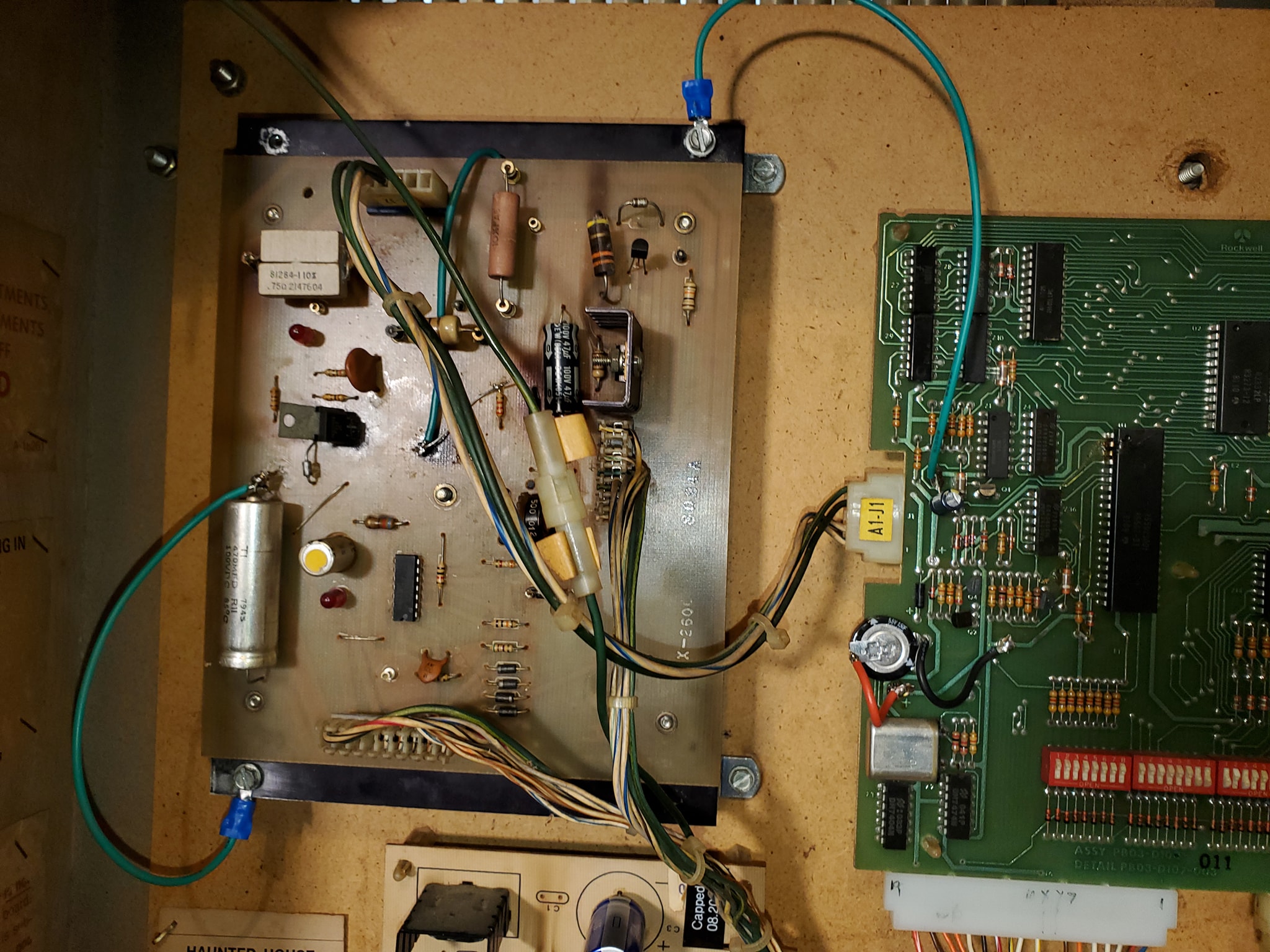
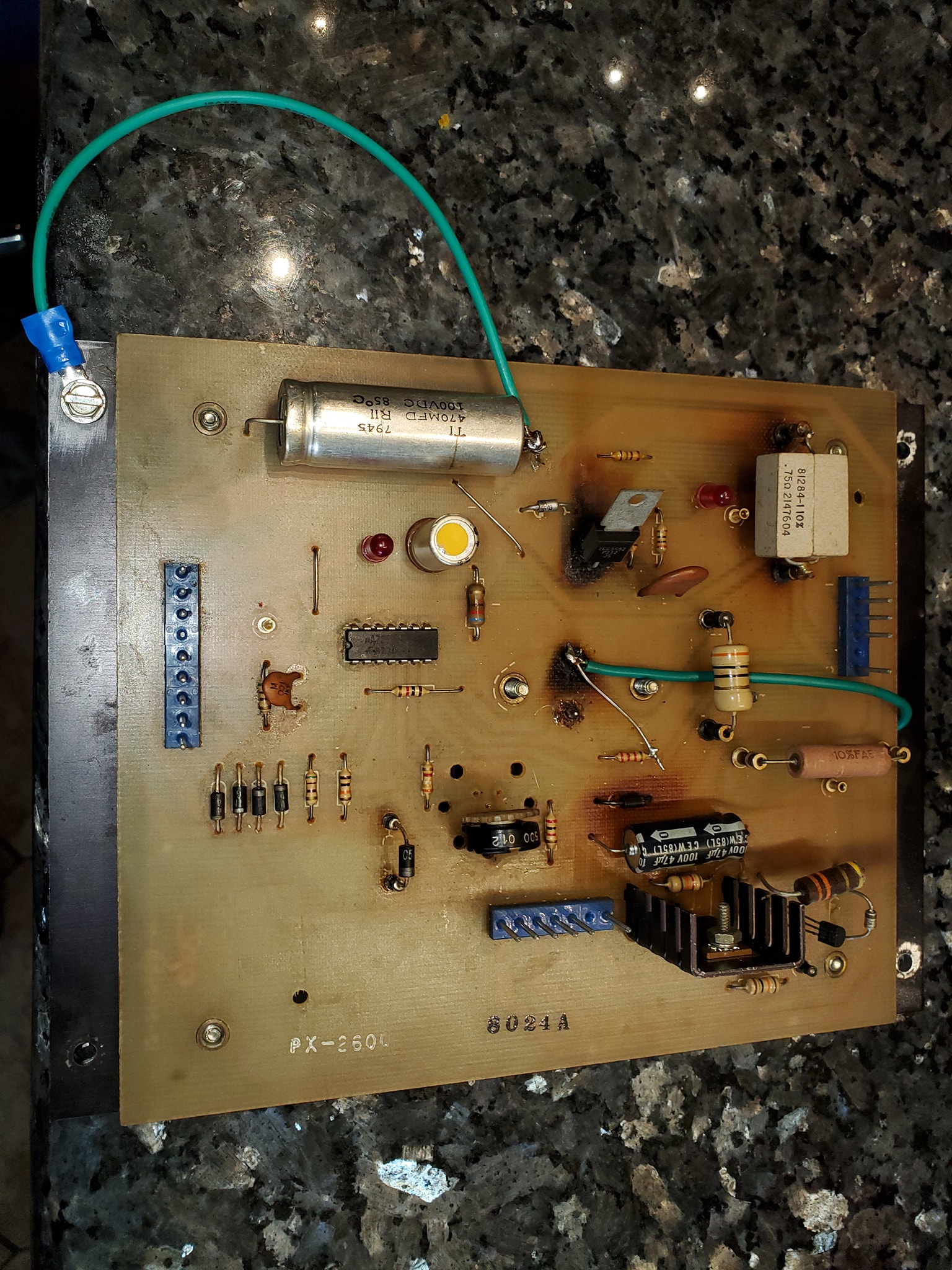
Now that I’ve got Haunted House running, it’s time to bulletproof the game – ideally you’d probably want to do the ground mods from the very beginning because in some cases, you might not be able to get the game working otherwise, but in this case, I managed to get the game to boot and appear to play well, so now we’re doing the required ground modifications to make the game more stable and reliable.
What’s actually involved in that?
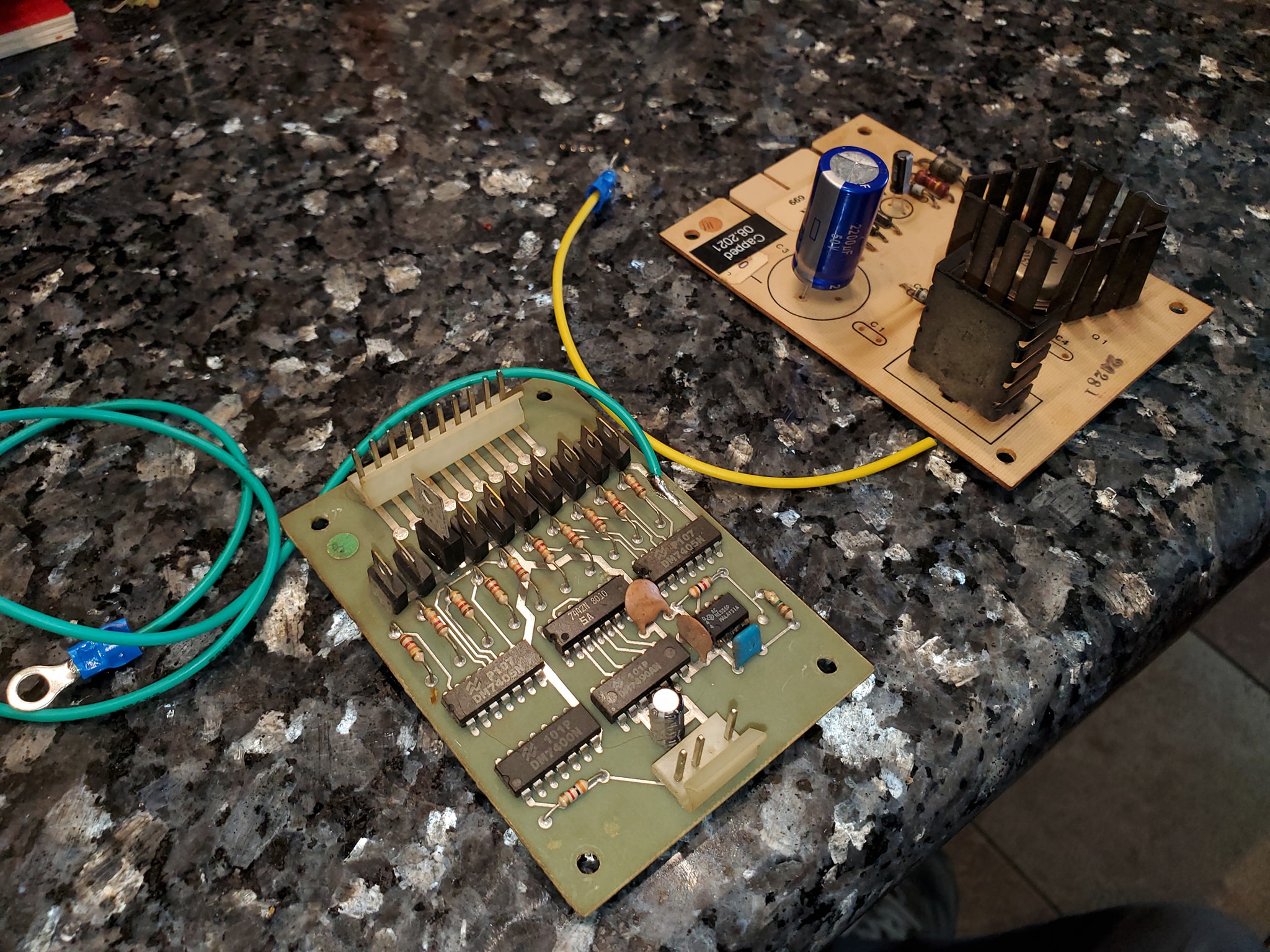
It’s pretty simple. Gottlieb used single-sided edge connectors (unlike Trifucon which has contacts on multiple sides) for most of their connections. Over time, these connectors tended to fail, either by the contact surface becoming oxidized, or the blades becoming fatigued and not making good contact. Since ground is so important, without a solid contact, the game can behave in a variety of different and unpredictable ways, from random reboots, to intermittent issues with everything from lights to sound to coil firing. The general rule with Gottlieb games is if you’re having a weird problem that isn’t consistently repeatable, there’s a good chance it’s related to the powertrain. The most obvious culprit in the power chain is going to be the ground/return lines.
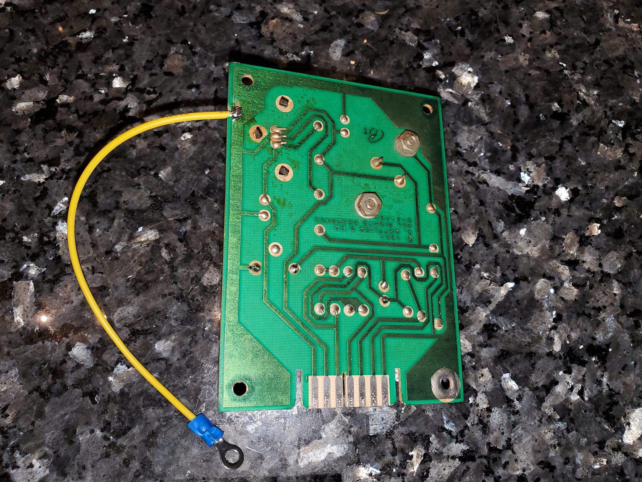
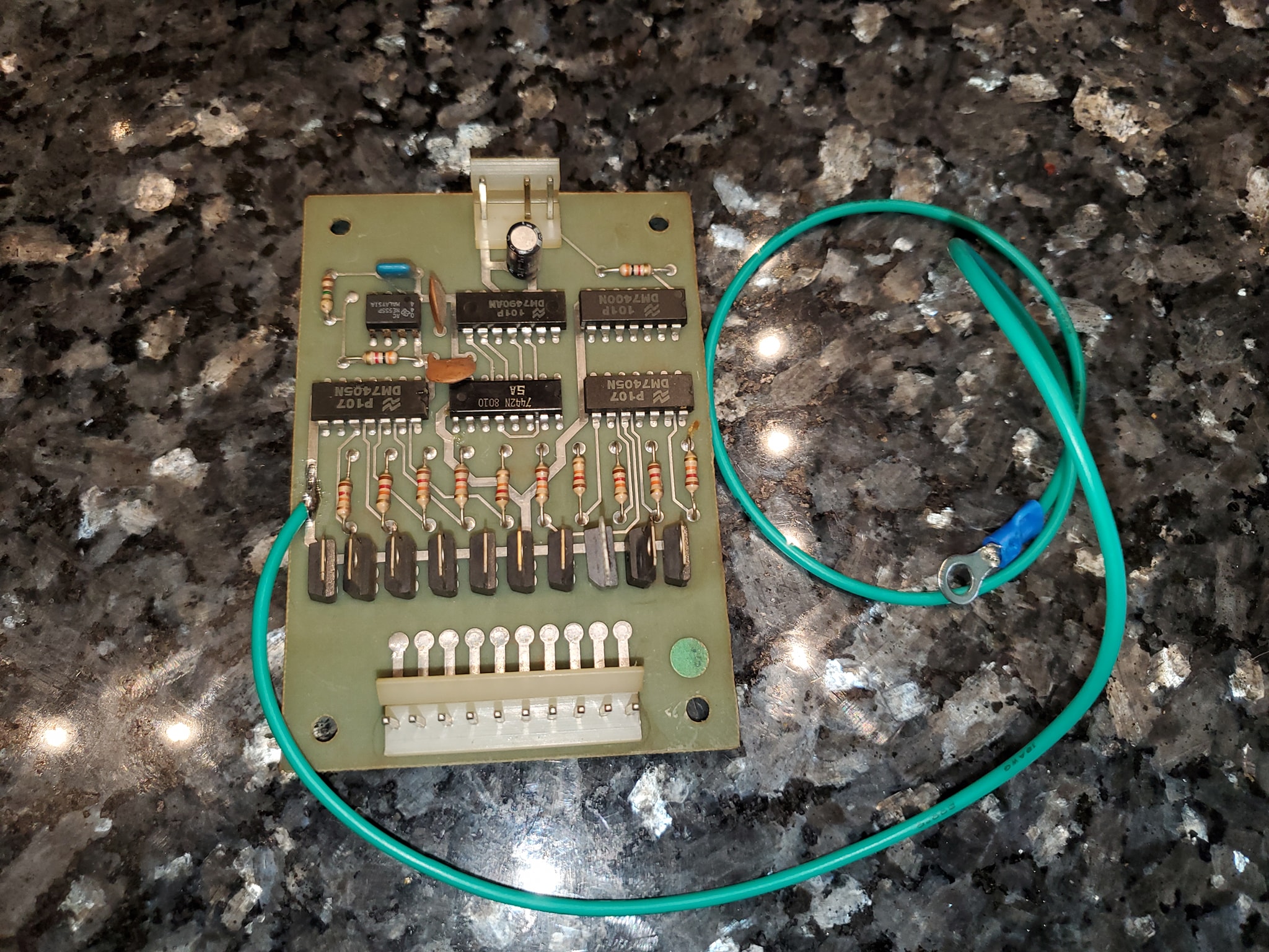
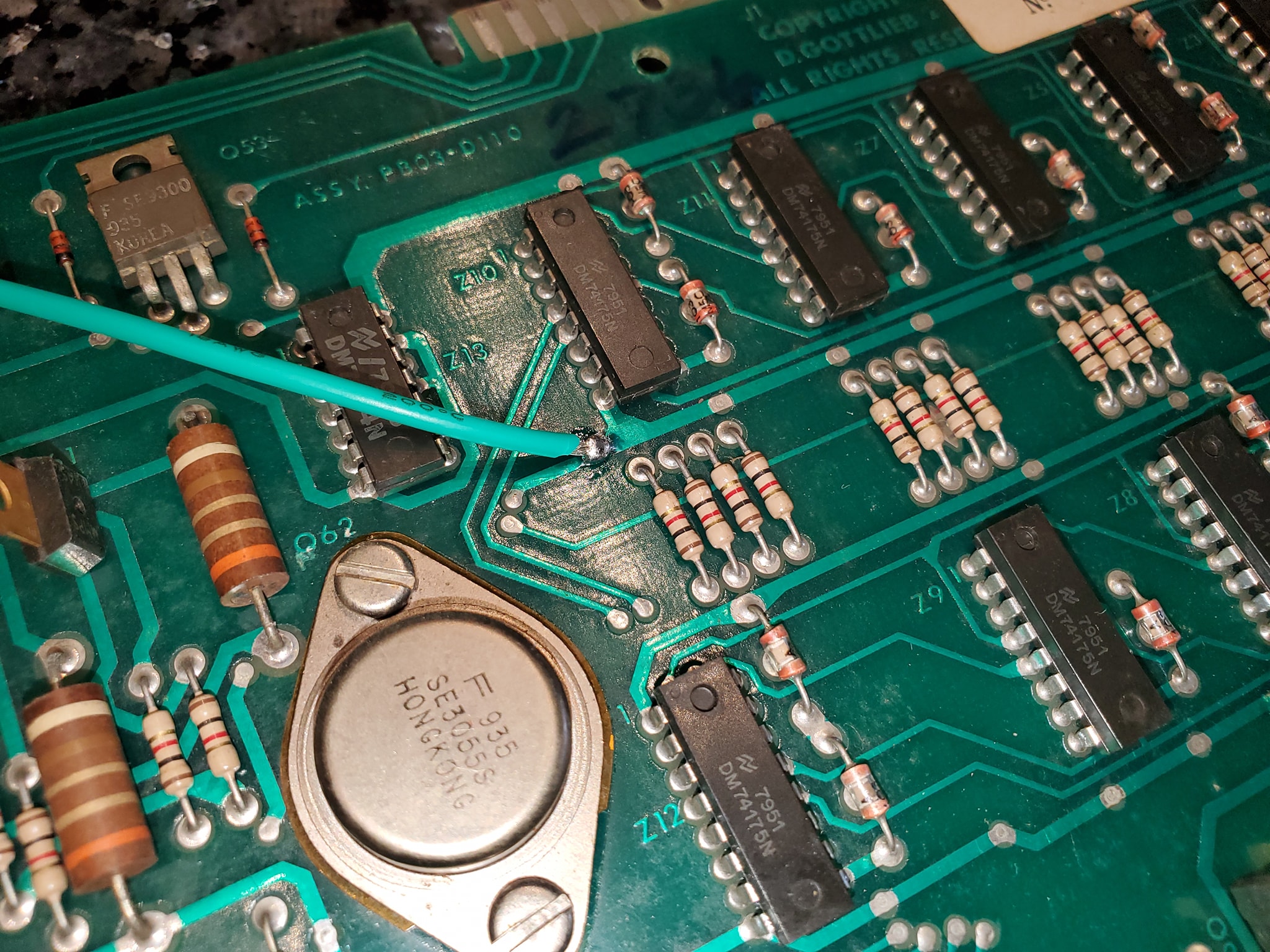
In-a-nutshell, the ground mods involve running an extra ground wire to tie all the different board’s ground lines to a common ground, and tie the head and the cabinet ground lines together — the only exception is you keep the 45v solenoid ground line separate (this is to ensure that if there’s a coil short, it doesn’t send high voltage to the rest of the game’s more sensitive components). Each board has a different recommended spot where you should tap into the ground, often it’s near one leg of a capacitor (which should also be changed if they’re original). Use 18 gauge wire (preferably green colored) and tap into each board with one end in the designated spot, then crimp a spade terminal on the other end and tie all the boards to a single ground plane (usually the metal bracket that mounts the power supply in the upper left corner — be sure to sand the paint off the area so you can make contact (alternatively you can also solder directly to the bracket.
Once you have all the boards tied to a single plane, you want to tie that to the head and the cabinet, by running wires from the power supply bracket to the metal frame in the head, and then one down into the cabinet to the transformer board, where you’ll find a ground backplane you solder to (on System 80B games, you’ll also want to take all the ground wires that terminate on the transformer board and tie them together, preferably eliminating the molex connectors they used which cause problems).
Click at the top of each image below for larger versions:
All the boards with mods – note the mpu board ground mod is to the top part of the capacitor on the left middleGround mods to the aux light board and sound card power supplyunderside of the sound board power supply showing ground tapaux light board ground tapNote the light green wire – this is the new ground line from the power supply bracket in the headground tap location on the driver boarddriver board ground tap completedlocation shown where protective coating is sanded off to solder ground tap on driver boardtap from MPU to main ground plane / power supply boardRecommended Gottlieb System 80 ground modifications – power supply boardSound and Speech board ground mod tapAlternate ground mod location for sys80 CPU board
This is an introduction to an up-and-coming technology that a small group of pinball and electronics enthusiasts are developing. A custom microcontroller that interfaces with Bally-35 MPUs and allows you to write customized rulesets, even completely re-theming games. This is the first part of a journey that I hope to take everybody on.
NOTE: This is a video I recorded several months ago that I forgot to make public, so I’m much further along.. But thought it might be interesting to show this early look at the development of this technology. Now there are etched boards that can be acquired.
This is the next video in my series of work on Paragon. After the first look (http://pinballhelp.com/first-look-bally-paragon-pinball/) I discovered there were still issues with the MPU board that were the result of continued corrosion even after the battery was removed and the board was supposedly cleaned. Whoever did the previous work didn’t clean the board enough and corrosion continued. I’m going to do my best to salvage the board.