A friend brought in a game to the shop that is a really beautiful Kiss game and we’re going to update it with new tech and make it better than ever.
Here are the following parts:
A friend brought in a game to the shop that is a really beautiful Kiss game and we’re going to update it with new tech and make it better than ever.
Here are the following parts:
Today I’m testing some new LED displays that come from Australia.
These new LEDs are a drop in replacement for the standard high voltage displays, but use less power and look almost identical to the original displays.
They’re produced by Wayne Hamilton out of Australia. Here is where you can find his products:
eBay: https://www.ebay.com.au/usr/omfug1190
GeekPCBs: https://geekpcbs.au/
I’ve encountered an odd problem with this Stern Walking Dead pinball game. The sound completely went out. But there is not a dedicated sound board. So what do you do? It’s a lot scarier than one would think…. This is part one describing what’s going on and what I’m doing about it…
I’m very excited I was able to pick up one of my grail games – an early 80s Bally Embryon. Here is some of my progress.
In the next video, I begin to go over what’s wrong with the game and work on it. First order of business is dealing with flippers – on these Bally games, there are some issues with EOS switches.
Next we move onto dealing with drop targets.
In this video designer Stephen Silver shows us the inner workings of the P3 system. It’s a very interesting and efficient design that makes the game surprisingly easy to service, with lots of features not found in typical pinball machines.
Now that the Haunted House is all restored, let’s do a video showcasing the gameplay and ruleset!


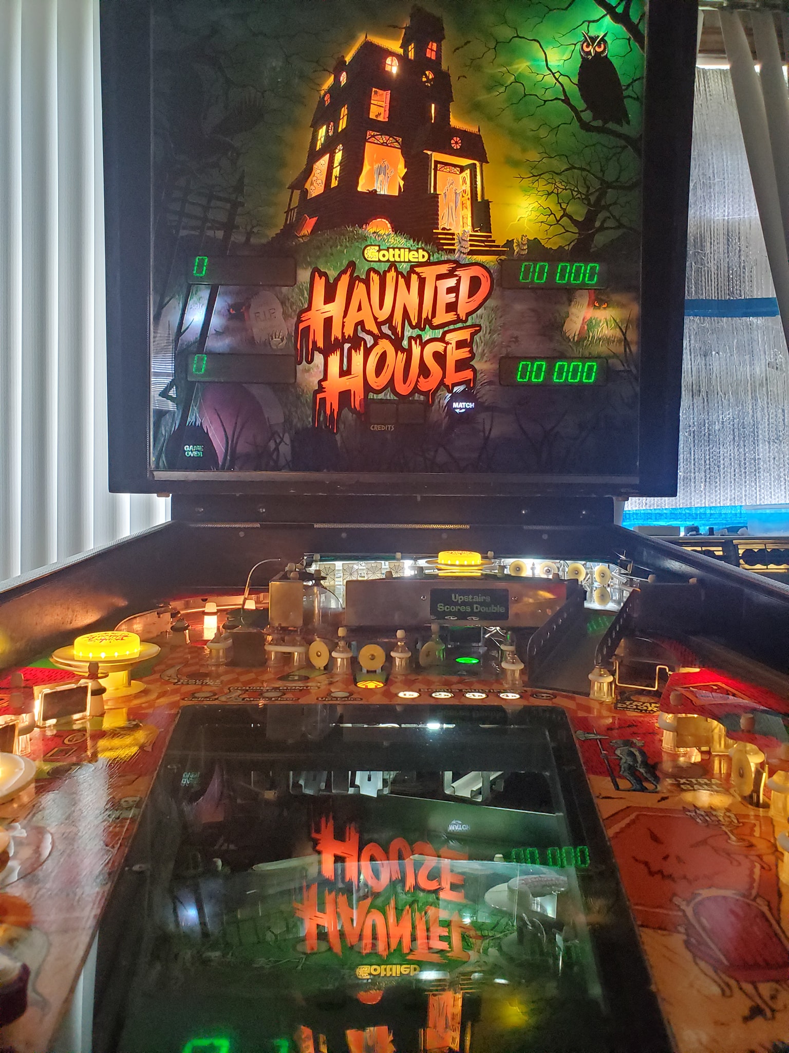


Now that I’ve got Haunted House running, it’s time to bulletproof the game – ideally you’d probably want to do the ground mods from the very beginning because in some cases, you might not be able to get the game working otherwise, but in this case, I managed to get the game to boot and appear to play well, so now we’re doing the required ground modifications to make the game more stable and reliable.
What’s actually involved in that?
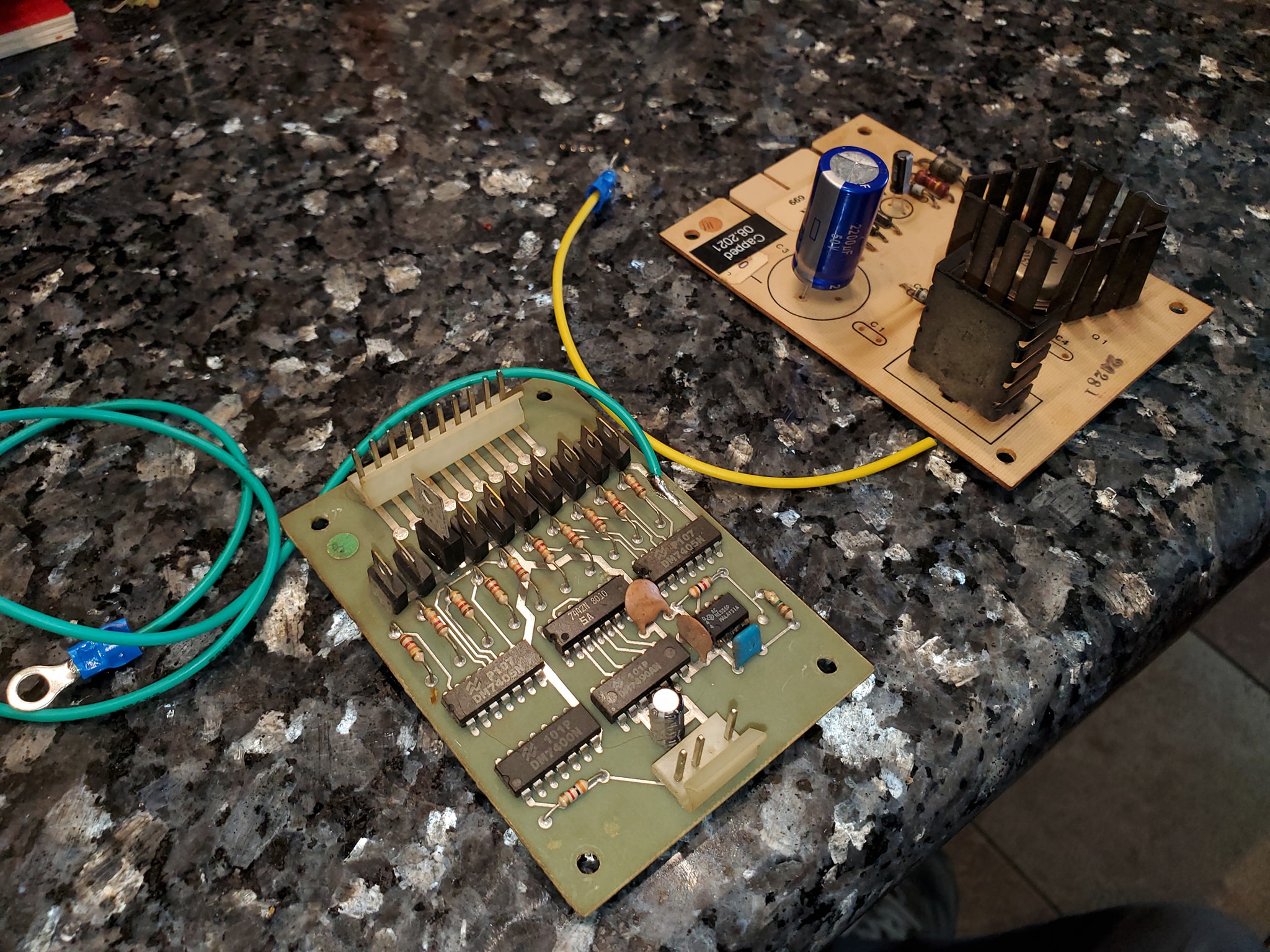
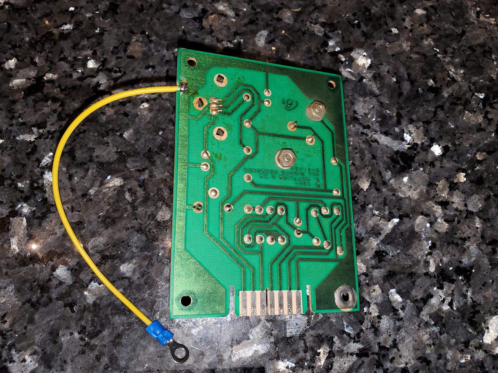
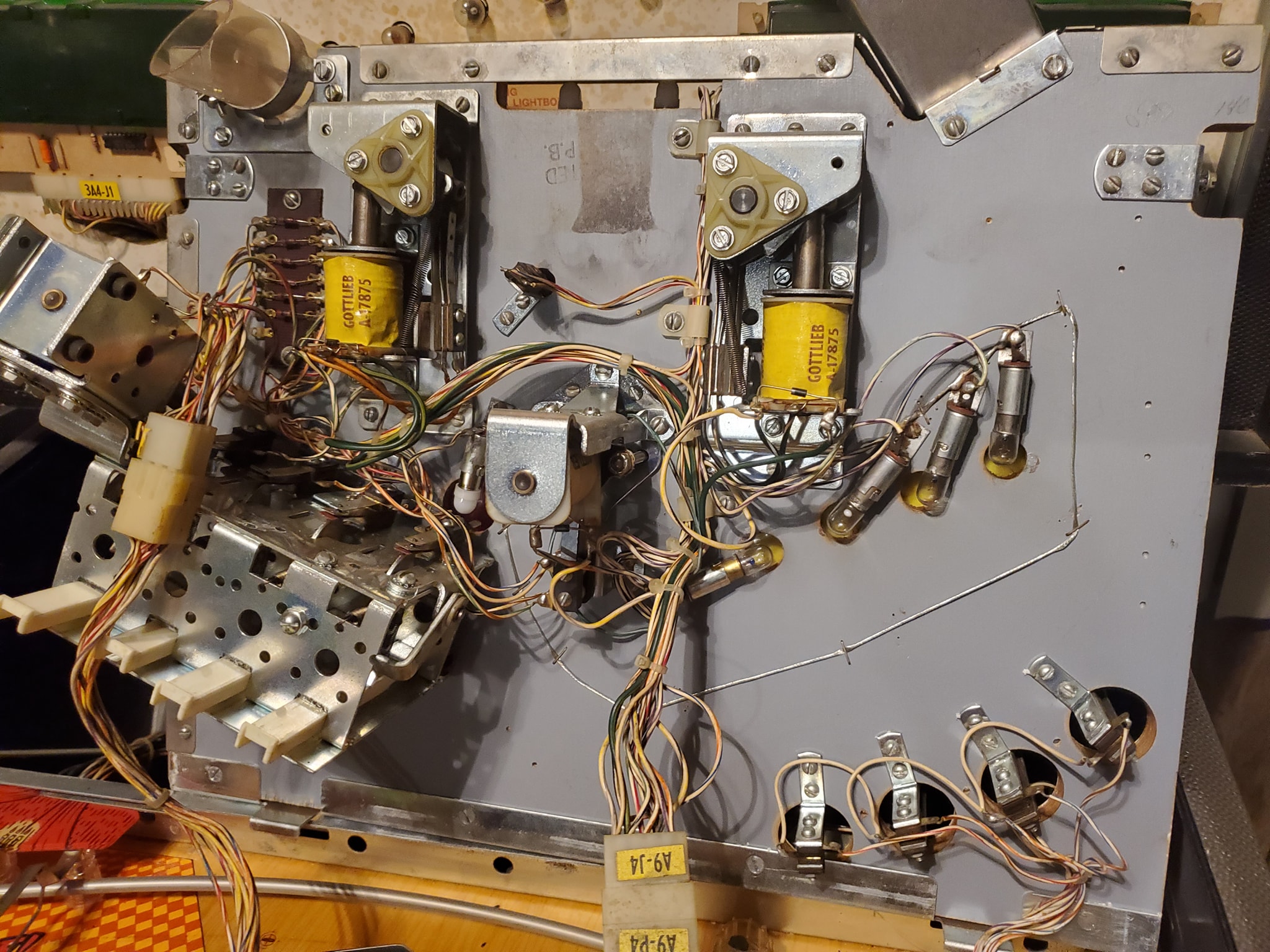
It’s pretty simple. Gottlieb used single-sided edge connectors (unlike Trifucon which has contacts on multiple sides) for most of their connections. Over time, these connectors tended to fail, either by the contact surface becoming oxidized, or the blades becoming fatigued and not making good contact. Since ground is so important, without a solid contact, the game can behave in a variety of different and unpredictable ways, from random reboots, to intermittent issues with everything from lights to sound to coil firing. The general rule with Gottlieb games is if you’re having a weird problem that isn’t consistently repeatable, there’s a good chance it’s related to the powertrain. The most obvious culprit in the power chain is going to be the ground/return lines.
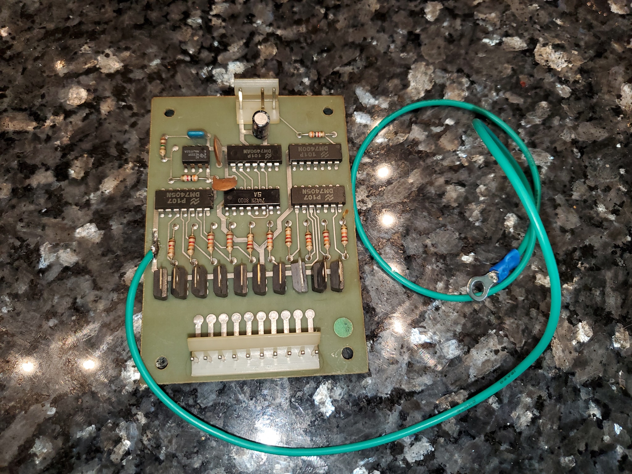
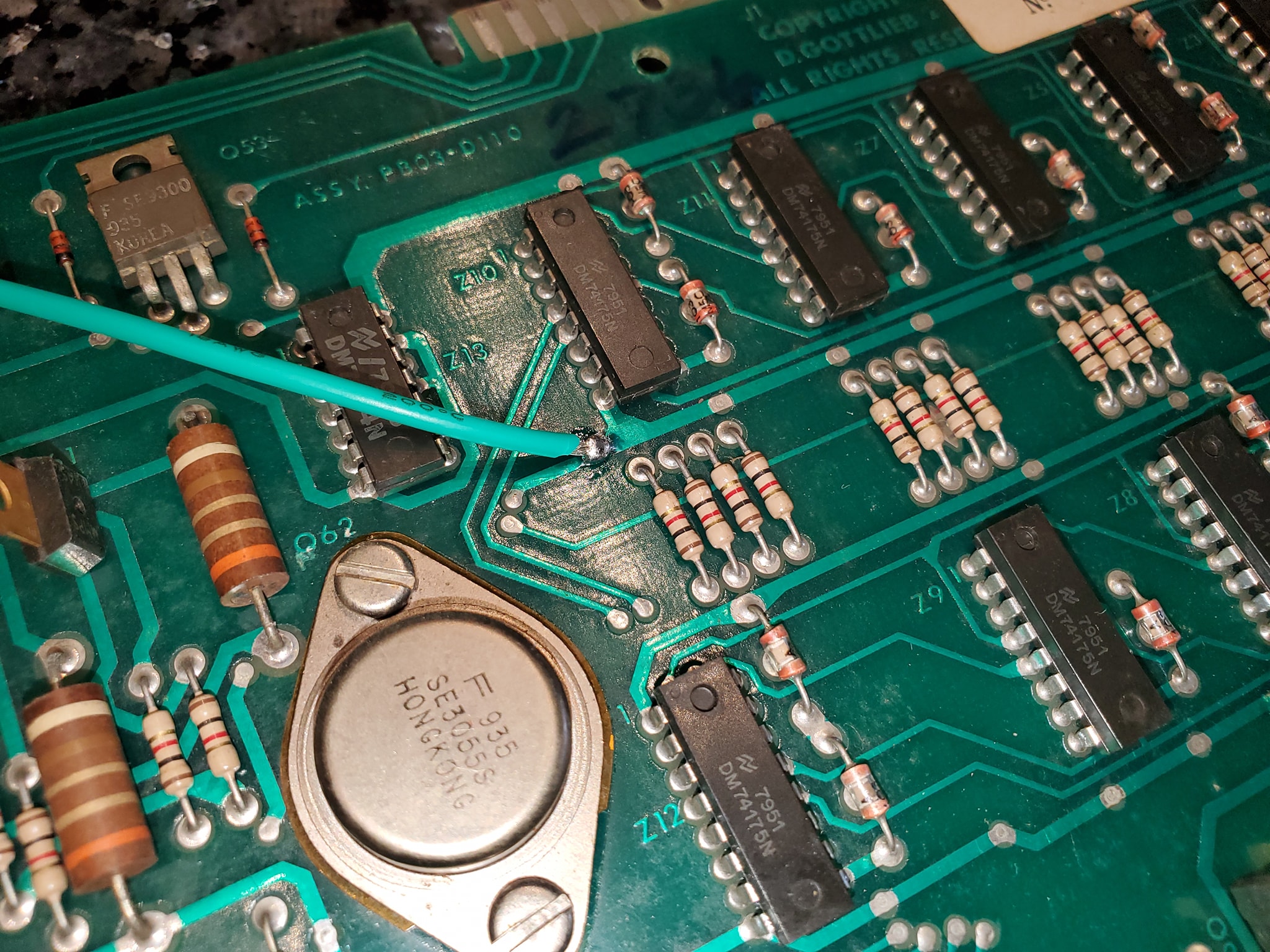
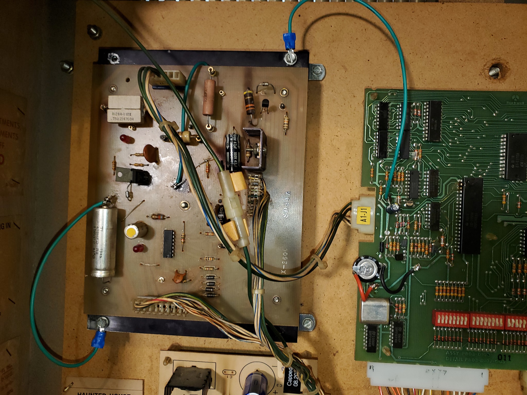
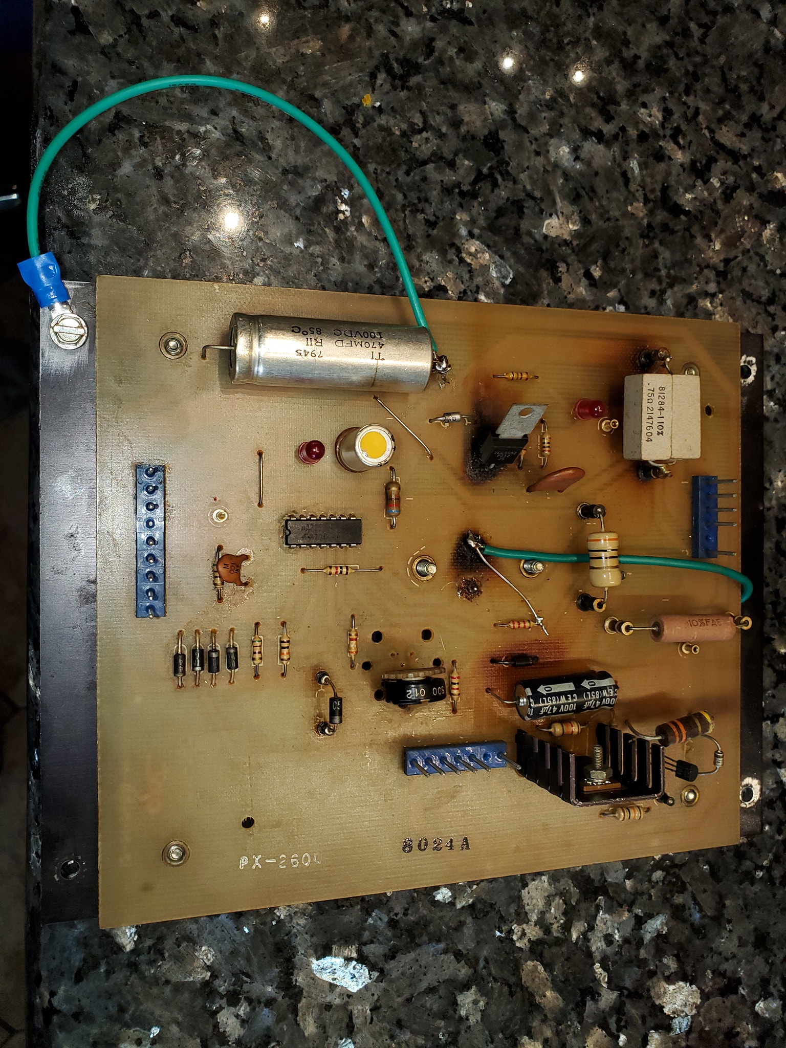
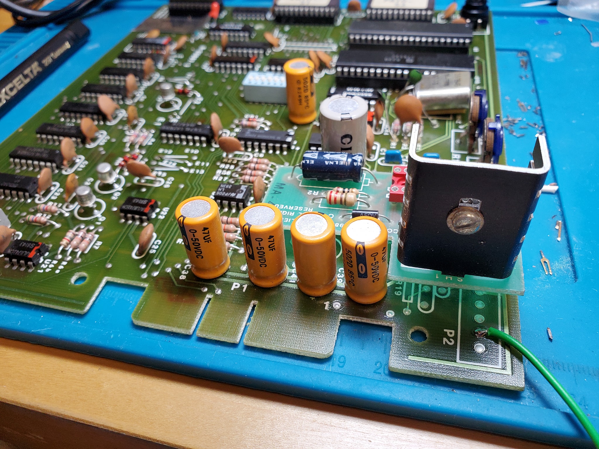
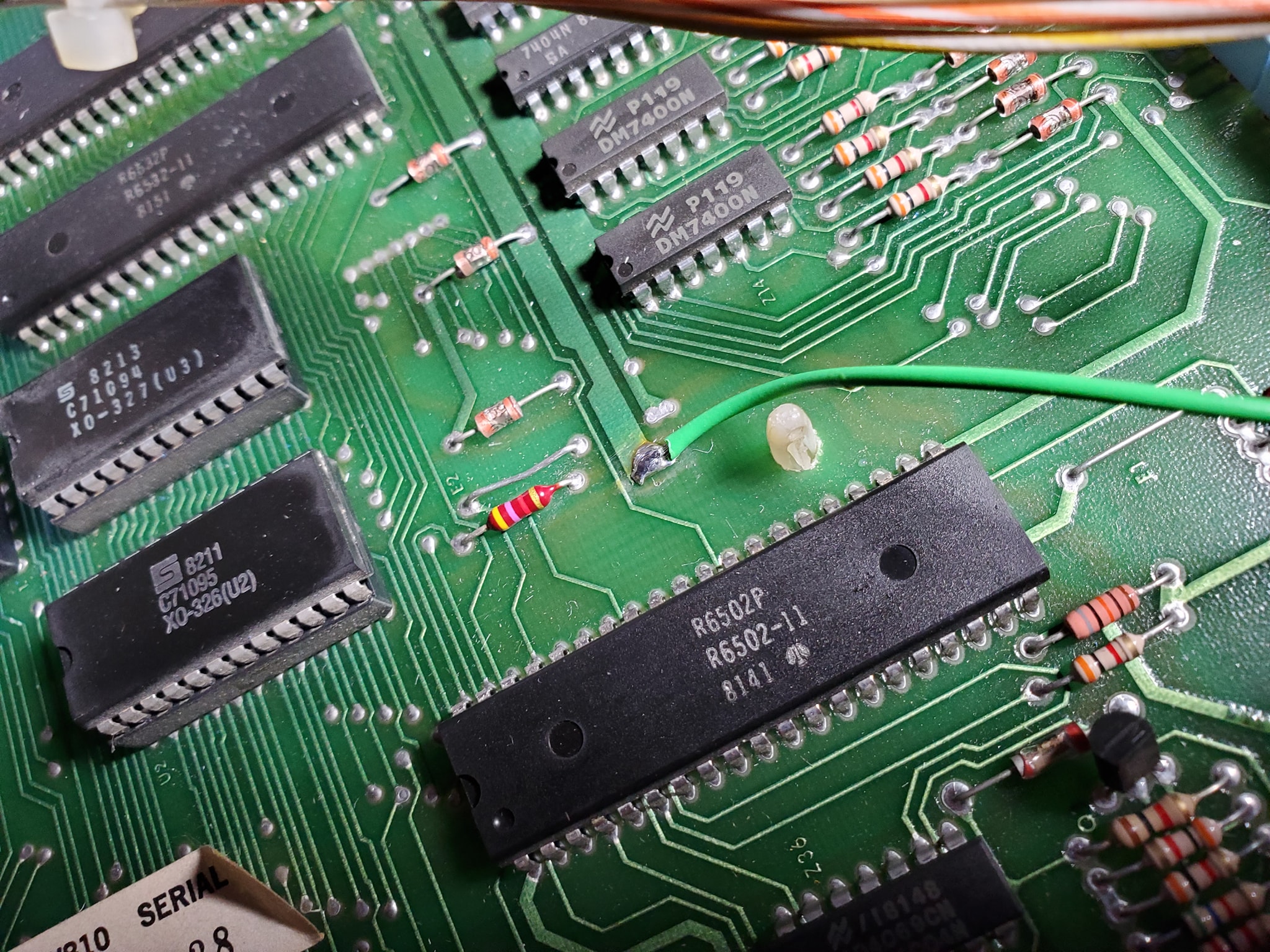
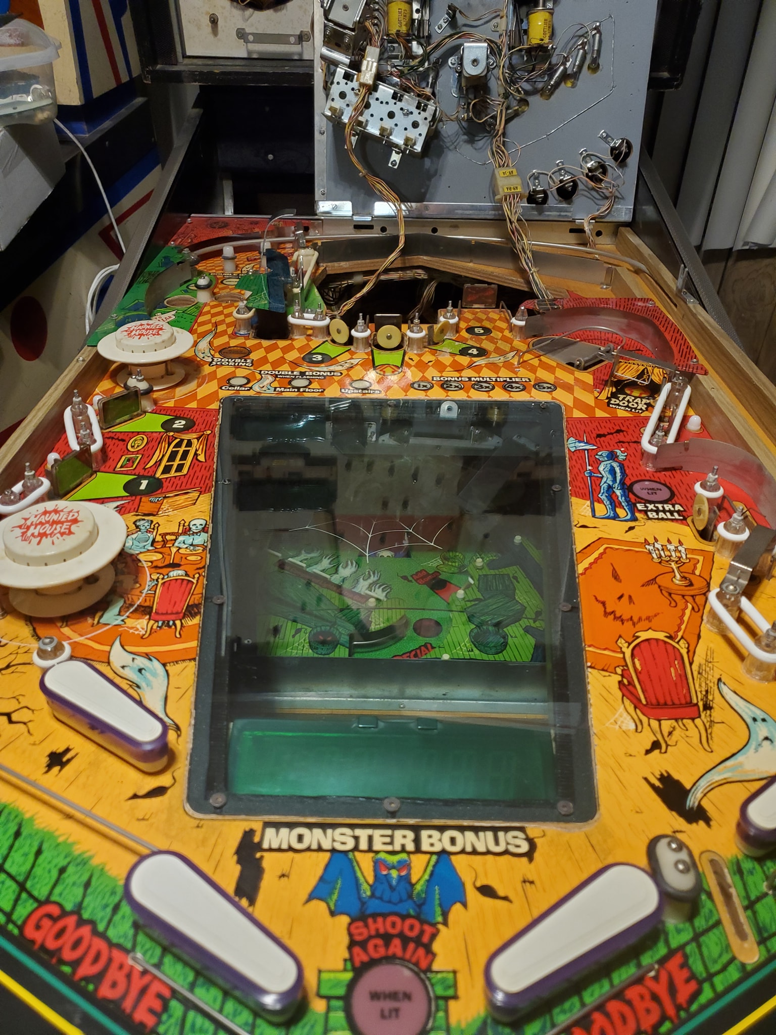
In-a-nutshell, the ground mods involve running an extra ground wire to tie all the different board’s ground lines to a common ground, and tie the head and the cabinet ground lines together — the only exception is you keep the 45v solenoid ground line separate (this is to ensure that if there’s a coil short, it doesn’t send high voltage to the rest of the game’s more sensitive components). Each board has a different recommended spot where you should tap into the ground, often it’s near one leg of a capacitor (which should also be changed if they’re original). Use 18 gauge wire (preferably green colored) and tap into each board with one end in the designated spot, then crimp a spade terminal on the other end and tie all the boards to a single ground plane (usually the metal bracket that mounts the power supply in the upper left corner — be sure to sand the paint off the area so you can make contact (alternatively you can also solder directly to the bracket.
Once you have all the boards tied to a single plane, you want to tie that to the head and the cabinet, by running wires from the power supply bracket to the metal frame in the head, and then one down into the cabinet to the transformer board, where you’ll find a ground backplane you solder to (on System 80B games, you’ll also want to take all the ground wires that terminate on the transformer board and tie them together, preferably eliminating the molex connectors they used which cause problems).
Click at the top of each image below for larger versions: