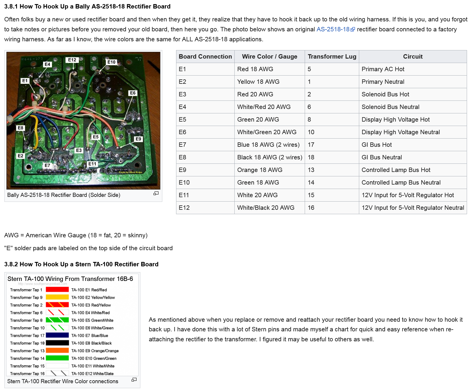
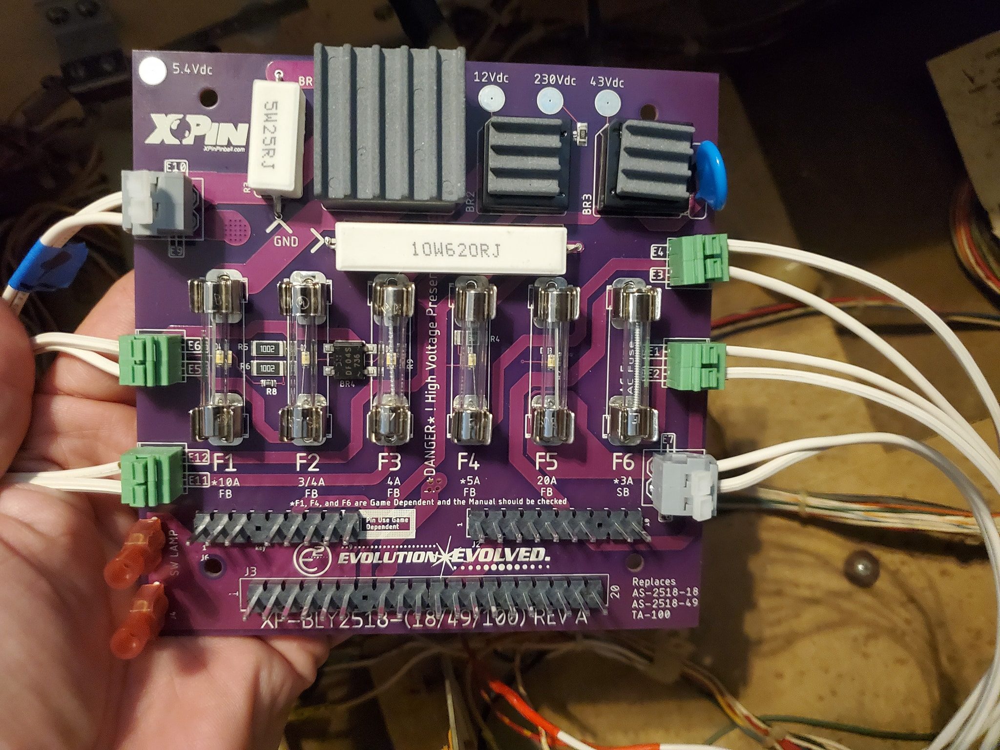
As part of the ongoing restoration of a 1979 Stern “Trident” pinball machine, here’s a series of videos outlining how to replace the rectifier board on these games. This varies a bit between Stern and Bally due to wire color codes. References are here.
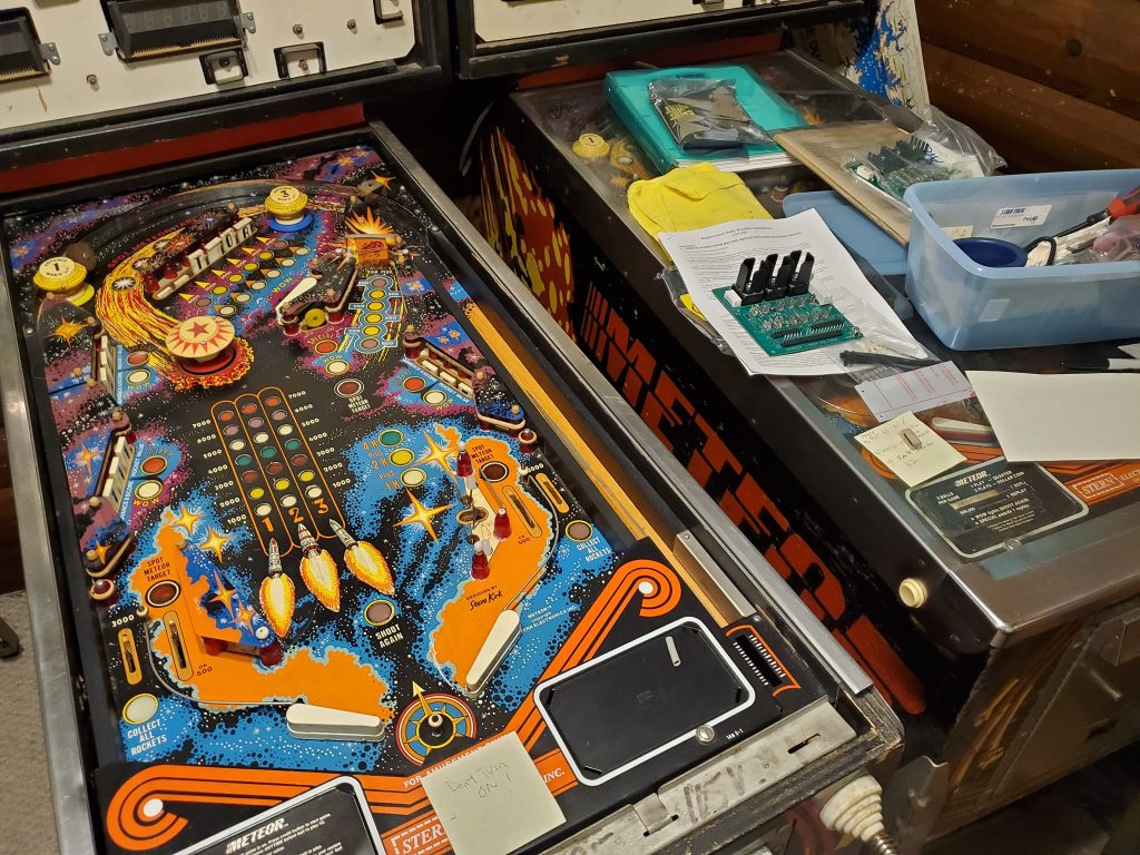
Let’s pull a game out of the barn and see what we have? Peer over my shoulder as I take a look for the first time, at a picked up game and see what it needs to be restored. From beginning to end, I will chronicle my progress taking a non-working game and making it play.
You ever run across one of those pinball deals that turns out to be so sweet, you are afraid you’re going to get mugged getting the game into your vehicle? This is one of those deals. A really amazing find that I didn’t expect..
Sometimes you make a pinball deal because the price is great, but you’re not sure if you can restore the game or even if you should. But if you’re patient, everything falls into place. This is one of those stories.
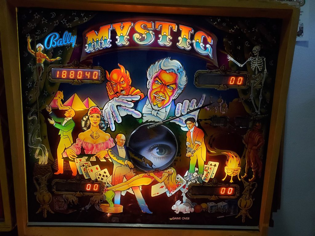
The other day as I was working on my Bally Mystic, I decided to upgrade the lighting in the backbox to LED and document what I consider to be a “tasteful” way to migrate from traditional incandescents to LED lighting. Some people complain about this but I think if you do it right, it’s a dramatic improvement, and in some ways is hard to tell from older style lighting. Let’s take a look!
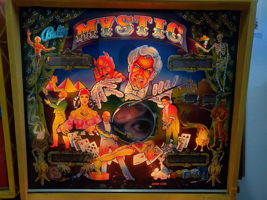
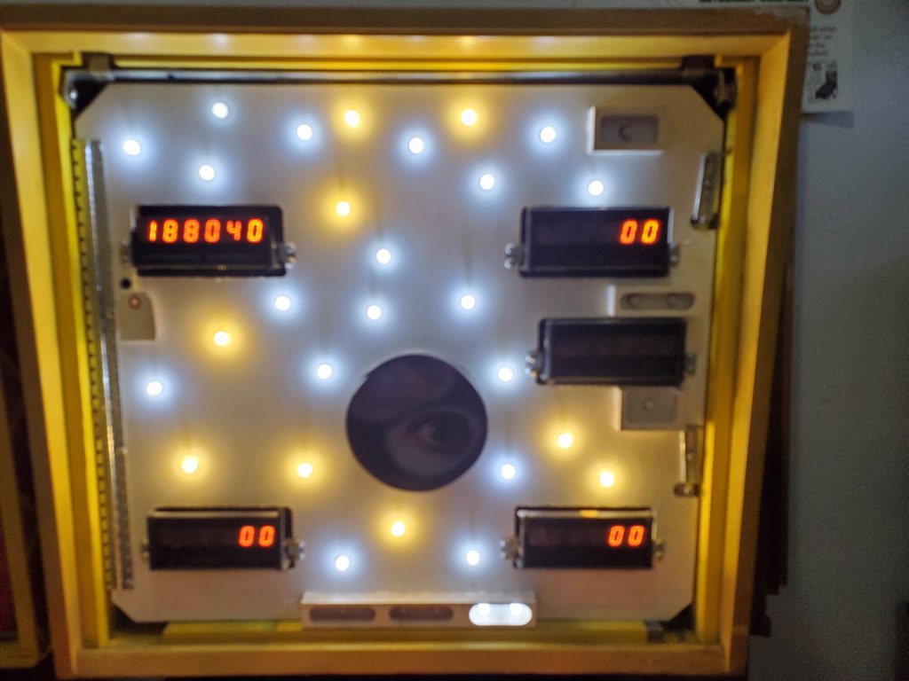
Here’s the game as it was before work. Traditional bulbs in the playfield and the backglass. You will notice that this is not your typical game. This is an early production/prototype that has a different cabinet color and a special 3-dimensional version of the center eye/pyramid imagery for the crystal ball.Here’s a close up of the original backglass lit with incandescent 44/47 type lights. Really beautiful artwork. NOTE that there’s more light shining ON the backglass in this picture, when compared with the last one below. This is probably due to the LEDs being brighter and my camera compensating by reducing the aperature or shutter speed. After removing the backglass I replaced the incandescent bulbs with LEDs. I used a combination of cool and warm white frosted 2SMD LEDs from Comet pinball. I put cool white over areas with the following colors: white, blue, green, and warm white over areas dominated by: red, yellow, amber. In this case I went more heavy on cool because they make the image “pop” a little more as you’ll see…And here’s the finished product. The whites are much whiter. The blues are bluer. I choose cool white for the crystal ball eye, and warm white for the pyramid (not pictured). NOTE that this is a mirrored glass, so there are only a few non-opaque areas so this isn’t the best example of how vivid and bright these LED-backed images can get. But IMO, a noticeable yet tasteful improvement.
Sometimes going after a pinball machine takes you on a weird and wacky experience. Here’s my story of running into a really weird character who did a number on me.
This is a story of one of those really rewarding moments when a rare game shows up, and also you have it given to you. Being in the right place at the right time pays off!