A friend brought in a game to the shop that is a really beautiful Kiss game and we’re going to update it with new tech and make it better than ever.
Here are the following parts:

A friend brought in a game to the shop that is a really beautiful Kiss game and we’re going to update it with new tech and make it better than ever.
Here are the following parts:
In this video, I am testing a technique that some have been talking about, using a special gel that will cure under UV light to fix playfield damage. I’m using what’s called “Bondic.”
Note I say “infrared” but I obviously mean “ultraviolet.”
What’s your experience with this product?
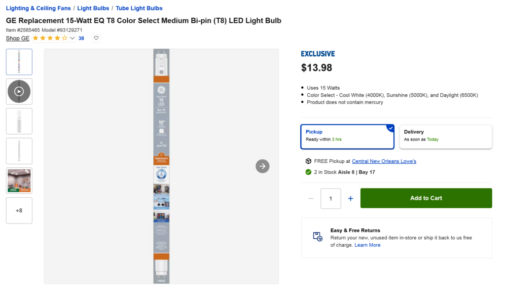
As work continues repairing this Frogger video arcade, I was planning to do a video on retrofitting the 18″ T8 fluorescent bulb that lights the marquee with an LED (and removing the ballast wiring) which is also used on some pinball machines from the 2000s, I discovered an even better lighting option you can probably find at your local Lowes. Check it out.
Here is the bulb in question:

I’m finally getting around to fixing my Bally Theater of Magic pinball. In this case, as is typical, the trunk stopped working. The trunk is not working at all, so let’s find out what’s wrong and I’ll also go into replacing the trunk opto board with a new and improved, German-made board. Will this fix all the problems? Watch and see….
Part 2: Work continues on the Bally Theater of Magic pinball – in this case, we’ve figured out why the trucnk wasn’t working even after installing a brand new, improved, aftermarket trunk board. The motor driver controller was shot! Now, while we’re bulletproofing the game, this is a good time to install the special Cliffy Protectors around the trunk to make sure there’s no damage to the plafield. In this video I go over how to lift the trunk out to be able to do this, among other things.
We finally got everything working on the Theater of Magic pinball – here’s a summary of everything that’s been done, along with an odd problem I had with an aftermarket proximity sensor.
An odd assortment of things are wrong on this TSPP pinball machine. Are they related? Let’s look into what’s wrong and where we should look to fix things?
This has now turned into a multi-part series where I also discover some other issues:
So here’s the take-away from the first 5 parts of this series.
Everything was basically inter-related (except I believe the slingshot and pop bumper coils were separate failures). The trouble with the ball trough opto led to the failure of the shooter lane coil. When the ball trough opto started failing, it signaled false switch closings, tricking the game into thinking balls were moving through the trough and causing the VUK to try to clear a problem, which caused multiple balls to go into the shooter lane. This happened faster than the auto-plunger could handle and once X number of balls went in there, the plunger could not clear them, and eventually the MPU sent too many “fire-the-coil” signals and blew the driver transistor — interesting that it blew the driver transistor before it melted the coil — I suspect either (or both) can happen in this circumstance.
What’s interesting about this, is that this problem could be compensated for by software. It’s also possible the other coil failures are the result of a similar characteristic: Not having a certain timeout or duty-cycle enforced on coils. Meaning… the software could check to make sure that if a coil is firing too much (say x amount of times in y time), that it knows there’s some kind or problem and then put the game into some sort of error state rather than blow the coil or the drivers. I know in some later games this happens… when errors are encountered, the game just stops trying to fire coils rather than blow them.
This obviously isn’t the case in some of these 2000-era Stern games. I’ve noticed this on several titles including WPT and NBA as well.
Unfortunately, there’s not likely to be a software fix available, so what is important is to keep an eye on game behavior and try to catch switch malfunctions before they blow things. Had I been told about the shooter lane situation earlier, I could have fixed the opto before it blew the driver transistor on the SDB.
Many games, especially older games would have their playfield mechs screwed directly into the wood with wood screws. On areas like bumper posts, these can take quite a beating, get loose and become stripped. Here’s a simple technique to repair stripped holes to make the screws bite back into the playfield.
After having this game on location for awhile, I thought I might report on what types of wear and tear and damage I’m running into, and what was wrong with the game. I think we’ve found a few “weak links” relating to parts that probably should last a little longer. Check it out: